Audi A4: Checking Pressures on Vehicles with Expansion Valve and Receiver/Dryer (with Internally Regulated Compressor)
General Information
 Note
Note
- Connect the A/C service station. Refer to → Chapter "A/C Service Station, Connecting".
- Observe the test requirements. Refer to → Chapter "Pressures, Checking".
- With the ignition switched off, check the pressure in the refrigerant circuit (using the service station). Refer to → Chapter "Refrigerant Circuit, Checking Pressure with Service Station".
The pressures with the ignition turned off meet the specifications.
- Start the engine.
- Bring the engine speed up to 2000 RPM.
- Observe the pressure gauge of the service station.
Note
- The switch pressures and design of refrigerant circuit switches are vehicle-specific.
- Pressures must be measured at service connections; component locations of these connections are vehicle-specific. Refer to → Heating, Ventilation and Air Conditioning; Rep. Gr.87; System Overview - Refrigerant Circuit (vehicle-specific repair manual).
Specified Values for the Refrigerant Circuit Pressures
High-Pressure Side:
Increasing from initial pressure (when connecting the pressure gauges) to a maximum of 20 bar (290 psi).
Low-Pressure Side:
Decreasing from initial pressure (when connecting pressure gauges) to the value in the graph.
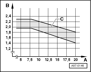
A - High pressure in bar (psi)
B - Low pressure in bar (psi)
C - Permissible tolerance range
Note
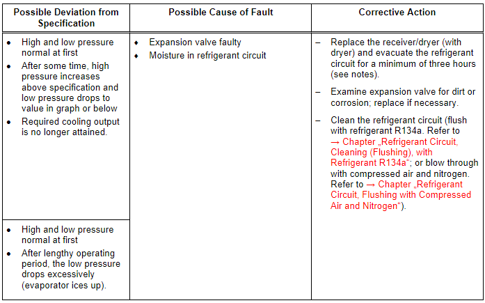
If no malfunction can be found and air conditioner operation is not OK when test is repeated, clean refrigerant circuit (flush using refrigerant R134a. Refer to → Chapter "Refrigerant Circuit, Cleaning (Flushing), with Refrigerant R134a"; or blow through using compressed air and nitrogen. Refer to → Chapter "Refrigerant Circuit, Flushing with Compressed Air and Nitrogen").
Note
If operation is not OK after cleaning refrigerant circuit (flushing with R134a. Refer to → Chapter "Refrigerant Circuit, Cleaning (Flushing), with Refrigerant R134a"; or blowing through using compressed air and nitrogen. Refer to → Chapter "Refrigerant Circuit, Flushing with Compressed Air and Nitrogen"), expansion valve must be replaced.
Note
- It is not initially necessary to clean the refrigerant circuit (flush using refrigerant R134a. Refer to → Chapter "Refrigerant Circuit, Cleaning (Flushing), with Refrigerant R134a"; or blow through using compressed air and nitrogen. Refer to → Chapter "Refrigerant Circuit, Flushing with Compressed Air and Nitrogen") when this problem occurs since normally, there is only a small quantity of moisture in the system which can be removed by lengthy evacuation.
- If problem involving moisture in refrigerant circuit only occurs after a lengthy operating period or only infrequently (low pressure drops below specification and evaporator ices up), it is sufficient to replace the dryer (adjust quantity of refrigerant oil). Refrigerant circuit is then to be evacuated for at least three hours.
Note
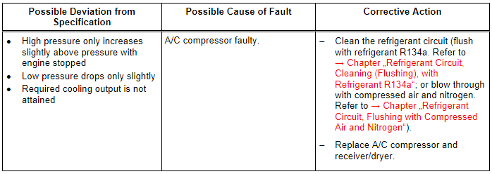
If air conditioner operation is not OK when test is repeated, install old expansion valve, clean refrigerant circuit (flush using refrigerant R134a. Refer to → Chapter "Refrigerant Circuit, Cleaning (Flushing), with Refrigerant R134a"; or blow through using compressed air and nitrogen. Refer to → Chapter "Refrigerant Circuit, Flushing with Compressed Air and Nitrogen"). Then replace the A/C compressor and receiver/dryer.
Note
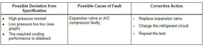
- If air conditioner operation is not OK when test is repeated, install old expansion valve, clean refrigerant circuit (flush using refrigerant R134a. Refer to → Chapter "Refrigerant Circuit, Cleaning (Flushing), with Refrigerant R134a"; or blow through using compressed air and nitrogen. Refer to → Chapter "Refrigerant Circuit, Flushing with Compressed Air and Nitrogen"). Then replace the A/C compressor and receiver/dryer.
- With this malfunction, evaporator may ice up although the quantity of refrigerant in circuit is OK.
Note
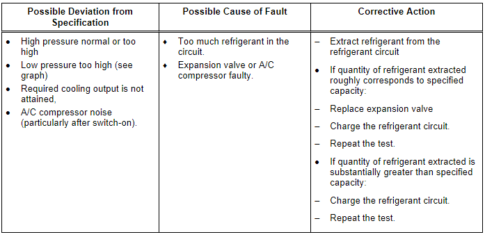
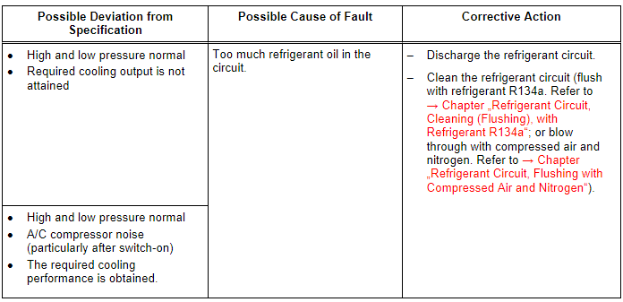
- Overfilling with refrigerant oil can occur if, for example, the compressor has been replaced without adjusting the quantity of refrigerant oil.
- If there is too much refrigerant oil in the circuit, the compressor must be drained and the receiver/dryer must be replaced. After cleaning the refrigerant circuit (flushing with refrigerant R134a. Refer to → Chapter "Refrigerant Circuit, Cleaning (Flushing), with Refrigerant R134a"; or blowing through using compressed air and nitrogen. Refer to → Chapter "Refrigerant Circuit, Flushing with Compressed Air and Nitrogen"), the correct quantity of refrigerant oil is filled into the circuit. Refer to → Chapter "Approved Refrigerant Oils and Capacities".
READ NEXT:
 Vehicles with Restrictor, Reservoir and A/C Compressor Regulator Valve
-N280- (Externally Regulated A/C Compressor), Checking Pressures
Vehicles with Restrictor, Reservoir and A/C Compressor Regulator Valve
-N280- (Externally Regulated A/C Compressor), Checking Pressures
Specified Values for the Refrigerant
Circuit Pressures
Note
Connect the Air Conditioning (A/C) service station. Refer to
→ Chapter "A/C Service Station, Connecting".
Observe the tes
Vehicles with Restrictor, Receiver/Dryer and A/C Compressor Regulator Valve
-N280-, Checking Pressures, Externally Regulated Compressor
General Information
Note
Connect the Air Conditioning (A/C) service station. Refer to
→ Chapter "A/C Service Station, Connecting".
Observe the test requirements. Refer to
→ C
SEE MORE:
Trailer
Driving with a trailer
General information
Your vehicle is primarily intended for transporting
people and luggage. However, if you drive
with a trailer, follow the technical requirements,
the operation and driving tips, and the legal regulations.
Driving with a trailer affects the vehicle's energy
Rearview camera and
peripheral cameras
Introduction
Applies to: vehicles with rearview camera/peripheral cameras
Fig. 126 Orientation line display when parking
Depending on the vehicle equipment, a rearview
camera or multiple peripheral cameras may be
available.
The rearview camera helps you to park or maneuver
using the orientation li
