Audi A4: Leak Detection on Refrigerant Circuit Using Leak Detection Kit -VAS6201A-
Vehicles with a High Voltage System (Hybrid Vehicles)
Read and follow all of the supplemental warnings for all work performed on vehicles with the high voltage system. Refer to → Chapter "Warnings when Working on Vehicles with High Voltage System" and → Electrical Equipment; Rep. Gr.93; General Warnings when Working on High Voltage System.
All vehicles
 Note
Note
- Certain leaks cannot or only with difficulty be found using an electric leak detection unit. Leak detection can be performed using Leak Detection Kit -VAS6201A-.
- Refrigerant and refrigerant oil escape when there is a leak in the refrigerant circuit. Generally, this oil remains in the vicinity of the leaking area. A small amount of fluorescent fluid must be added into refrigerant circuit so that this oil becomes visible under UV light. This fluid (PAG oil with an additive that lights up under UV light) is added into the refrigerant circuit and distributes itself with the refrigerant oil when the A/C system is switched on.
- A/C system must be operated for a minimum of 60 minutes so that the additive distributes itself in the entire refrigerant circuit (compressor must be running). Depending on the size of the leak, it may become visible under UV light within that time.
- Refrigerant oil with additive that lights up under UV-light can be added directly with an open circuit or be pumped into a filled circuit via service connection on the low pressure side using Leak Detection Kit - Hand Pump w/Cartridge -VAS6201/1- (from Leak Detection Kit -VAS6201A-).
- If the UV-leak detection additive is added to a filled refrigerant circuit via the service connection on the low pressure side, a small amount of it remains in the service connection. Carefully remove this residual amount so that a leaking area is not detected erroneously upon a later leak detection.
- If a component in which UV-leak detection additive has been added is being replaced on a circuit, thoroughly clean the connection areas to the other components after assembling the refrigerant circuit. The UV-leak detection additive residue may register erroneously as leaking areas during later leak detection.
- Refrigerant oil as well as UV-leak detection additive get into the service station when evacuating a refrigerant circuit. The refrigerant oil is separated from refrigerant in oil collector of service station and removed from the service station via the draining device. The refrigerant oil drained off must not be poured back in. It must be replaced with new refrigerant oil.
- If leak detection fluid was filled already in a refrigerant circuit for an earlier repair, note the following: Only add new leak detection fluid if the refrigerant oil will be replaced. If only a portion of refrigerant oil was replaced, only top-off with a corresponding amount of leak detection fluid as well. For example, if 100 ml of refrigerant oil was replaced in a vehicle with 250 ml, add only 1 ml (cm3) of UV-leak detection additive.
- Certain materials and their connections (for example, oxidation products on aluminum components, corrosion protection growth, etc.) also light up under UV-light.
- Depending on the version of the A/C service station, UV-leak detection additive can also be added directly at the top. Refer to the operating instructions that come with the A/C service station.
To prevent more refrigerant than is necessary for the leak test from venting into the air, proceed as follows with the refrigerant circuit completely empty:
- Evacuate the refrigerant circuit with the A/C service station. Refer to → Chapter "Refrigerant Circuit, Discharging with Service Station".
Note
- If a larger leak is found during evacuation, find and repair it as described. Refer to → Chapter "Finding Leaks via Vacuum Test using A/C Service Station or Nitrogen Pressure Testing" and → Chapter "Refrigerant Circuit, Discharging with Service Station".
- The UV-leak detection additive can also be filled in a filled or open refrigerant circuit with the Leak Detection Kit -VAS6201A-.
If no leak is found during evacuation or there is a leak that is so small that the location cannot be found, proceed as follows.
- Add the UV-leak detection additive using the A/C service station to the refrigerant circuit.
- Add UV-leak detection additive using the Leak Detection Kit -VAS6201- in the refrigerant circuit.
Add the UV-leak detection additive using the A/C service station to the refrigerant circuit.
- Add the UV-leak detection additive and the prescribed refrigerant amount using the A/C Service Station to the refrigerant circuit. Refer to → Chapter "Refrigerant R134a Capacities".
Note
Add 2.5 +- 0.5 cm3 of UV-leak detection additive for a refrigerant circuit with a refrigerant capacity of 100 to 150 cm 3 with the Leak Detection Kit -VAS6201- for the Leak Detection Kit -VAS6201-. If the refrigerant oil capacity in the refrigerant circuit is larger, then more UV leak detection additive must be added accordingly (for example, 5.0 +- 0.5 cm3 for a refrigerant circuit with a refrigerant oil capacity of 250 cm 3. When adding the UV-leak detection additive using the A/C service station, consult the corresponding Owner's Manual as the required amount may vary. For the relevant refrigerant oil quantities in the refrigerant circuit. Refer to → Chapter "Approved Refrigerant Oils and Capacities".
Special tools and workshop equipment required
- A/C service station with the option for adding the UV-leak detection additive to the refrigerant circuit. Refer to the Parts Catalog (Tools; Special Tools and Equipment: A/C and Heating).
- Approved leak detection additive. Refer to the Parts Catalog (Tools; Special Tools and Equipment: A/C and Heating).
- Leak Detection Kit - Cleaning Solution -VAS6201/3--3-
- UV Leak Detection Lamp -VAS6201/4A--4-
- Leak Detection Kit - Eye Protection -VAS6201/6--5-
- Leak Detection Kit - Label -VAS6201/7--6-
- Apply a label near the service connection stating that UV-leak detection additive was added to the refrigerant circuit.
- Start the A/C system.
Note
- A/C system must be operated for a minimum of 60 minutes so that the additive distributes itself in the entire refrigerant circuit (compressor must be running). Depending on the size of the leak, it may become visible under UV light within that time.
- Depending on the size and location of the leak, it can now last up to several days until enough refrigerant oil with UV-leak detection additive flows out to clearly determine the leaking area.
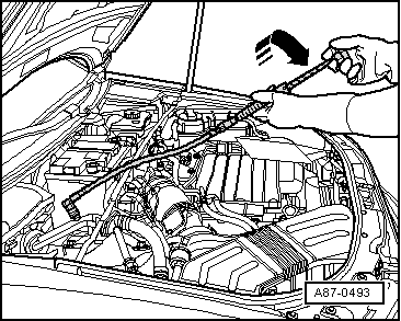
- Find the leak in the refrigerant circuit with the UV Lamp -VAS6196/4-.
Add UV-leak detection additive using the Leak Detection Kit -VAS6201- in the refrigerant circuit
Special tools and workshop equipment required
- Leak Detection Kit -VAS6201A-
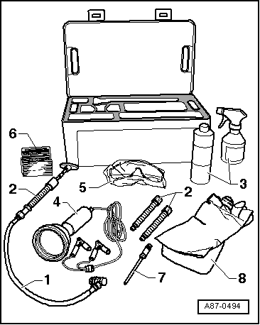
The Leak Detection Kit -VAS6201A- includes the following tools. Refer to the Parts Catalog (Tools; Special Tools and Equipment: A/C and Heating).
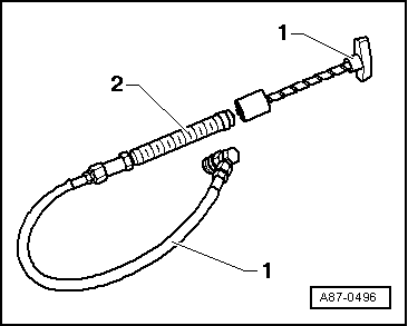
1 - Leak Detection Kit - Hand Pump w/Cartridge -VAS6201/1-
2 - Leak Detection Kit - Cartridge -VAS6201/2- (with UV-leak detection additive)
3 - Leak Detection Kit - Cleaning Solution -VAS6201/3-
4 - UV Leak Detection Lamp -VAS6201/4A-
5 - Leak Detection Kit - Eye Protection -VAS6201/6-
6 - Leak Detection Kit - Label -VAS6201/7-
7 - Leak Detection Kit - Filler Tube -VAS6201/8-
8 - Leak Detection Kit - Hand Protection -VAS6201/9-
Note
- Described in the following are instructions for how to pour the UV-leak detection additive into the refrigerant circuit using the Leak Detection Kit -VAS6201A-. If the UV-leak detection additive is added to the refrigerant circuit with the help of other tools (for example, with the A/C service station) read the applicable operating instructions.
- The following is the given amount of UV-leak detection additive that is to be added to a refrigerant circuit with a refrigerant oil quantity of 100 to 150 cm 3 using the Leak Detection Kit -VAS6201A- (2.5 +- 0.5 cm3). If the refrigerant oil capacity in the refrigerant circuit is larger, then more UV leak detection additive must be added accordingly (for example, 5.0 +- 0.5 cm3 for a refrigerant circuit with a refrigerant oil capacity of 250 cm 3. For the relevant refrigerant oil quantities in the refrigerant circuit. Refer to → Chapter "Approved Refrigerant Oils and Capacities".
- If the UV-leak detection additive is added to the refrigerant circuit with the help of other tools (for example, with the A/C service station), observe the prescribed quantities of UV-leak detection additive given in the corresponding operating instructions.
Adding UV-leak detection additive when the refrigerant circuit is empty
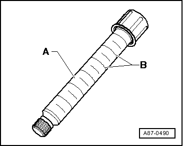
The cartridge -A- contains 15.4 ml of UV-leak detection additive (one unit -B- corresponds to 2.5 ml).
- Assemble the Leak Detection Kit -VAS6201A--1- with the cartridge -2-Leak Detection Kit - Cartridge -VAS6201/2-.
- Insert the Leak Detection Kit - Filler Tube -VAS6201/8-. Refer to → Anchor-item 7- into the hand pump.
- Open the hand pump service valve.
Note
- UV-Leak detection additive is best added to the empty refrigerant circuit via a service connection or an opened connection.
- If the refrigerant circuit is empty, then it is better to add the UV-leak detection additive via a connection point (for example, when the connection point is already open). This way no UV-leak detection additive remains in the service connection and the connection does not need to cleaned.
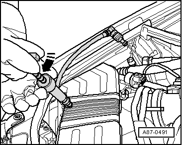
- Add the UV-leak detection additive to the refrigerant circuit via a service connection.
- Add the UV-leak detection additive to the refrigerant circuit via an opened connection.
Add the UV-leak detection additive to the refrigerant circuit via an opened connection
- Open an easily accessible connection point on the refrigerant circuit
- Cover the area around connection point with foil or absorbent paper.
- Hold the tube upwards.
- Tighten the hand pump handle just enough until the UV-leak detection additive comes out of the tube.
- Add 2.5 +- 0.5 ml (Milliliter = cm3) of UV-leak detection additive to the refrigerant circuit (for a refrigerant circuit with a refrigerant oil capacity from 100 to 150 cm3).
Note
If UV-leak detection additive was already added to the refrigerant circuit for an earlier repair, note the following: Only add new UV-leak detection additive if the refrigerant oil will be replaced. If only a portion of the refrigerant oil was replaced, only add a proportionate amount of the UV-leak detection additive. For example, if 100 ml of refrigerant oil was replaced in a vehicle with 250 ml, add only 2 ml (cm3) of UV-leak detection additive.
- Replace the O-ring seal at the opened connection point.
- Assemble the refrigerant circuit.
- Apply a label near the service connection stating that leak detection fluid was added to the refrigerant circuit.
- Evacuate and recharge the refrigerant circuit according to specification. Refer to → Chapter "Refrigerant Circuit, Discharging with Service Station" and → Chapter "Refrigerant Circuit, Charging with Service Station".
- Start the A/C system.
Note
- A/C system must be operated for a minimum of 60 minutes so that the additive distributes itself in the entire refrigerant circuit (compressor must be running). Depending on the size of the leak, it may become visible under UV light within that time.
- Depending on the size and location of the leak, it can now last up to several days until enough refrigerant oil with additive flows out to determine definitely the leaking area.
- Find the leak in the refrigerant circuit with the UV Lamp -VAS6196/4-.
Adding UV-leak detection additive when the refrigerant circuit is full
Note
- If leak detection fluid was filled already in a refrigerant circuit for an earlier repair, note the following: Only add new leak detection fluid if the refrigerant oil will be replaced. If only a portion of refrigerant oil was replaced, only top-off with a corresponding amount of leak detection fluid as well. For example, if 100 ml of refrigerant oil was replaced in a vehicle with 250 ml, add only 1 ml (cm3) of UV-leak detection additive.
- A small quantity of UV-leak detection additive remains in the service connection. Carefully remove this residual amount so that a leaking area is not detected erroneously upon a later leak detection.
The cartridge -A- contains 15.4 ml of UV-leak detection additive (one unit -B- corresponds to 2.5 ml).
- Switch off ignition.
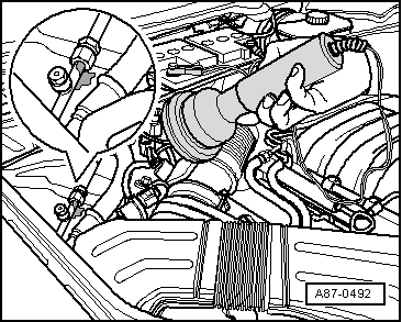
- Remove sealing cap from service connection of low pressure side in refrigerant circuit.
- Assemble the Leak Detection Kit -VAS6201A--1- with the cartridge -2-Leak Detection Kit - Cartridge -VAS6201/2-.
- Insert Leak Detection Kit - Filler Tube -VAS6201/8--7-into service coupling and open service coupling by screwing in handwheel. Hold the hose upward and tighten the handle of the hand pump just enough until the UV-leak detection additive starts to emerge from the tube.
Note
Make sure hand pump hose is completely filled with refrigerant.
- Close the service coupling and remove tube from the retainer.
- Cover the area around the service connection on the vehicle with foil or absorbent paper.
- Connect the filler device to the refrigerant circuit service connection on the vehicle.
- Open the service connection by screwing in the handwheel.
- Turn the hand pump handle to add 2.5 +- 0.5 ml (Milliliter = cm3) UV-leak detection additive to the refrigerant circuit (for a refrigerant circuit with a refrigerant oil quantity from 100 to 150 cm3).
- Remove the filling device from the service connection.
- Remove the rest of the UV-leak detection additive from the service connection, for example using absorbent paper.
- Seal the service connection with the sealing cap.
- If necessary, clean the area around service connection using cleaning solution.
- Apply a label near the service connection stating that leak detection fluid was added to the refrigerant circuit.
- Start the A/C system.
Note
- A/C system must be operated for a minimum of 60 minutes so that the additive distributes itself in the entire refrigerant circuit (compressor must be running). Depending on the size of the leak, it may become visible under UV light within that time.
- Depending on the size and location of the leak, it can now last up to several days until enough refrigerant oil with additive flows out to determine definitely the leaking area.
- Find the leak in the refrigerant circuit with the UV Lamp -VAS6196/4-.
Detecting leaks on the refrigerant circuit using UV Lamp -VAS6196/4-
 WARNING
Do not look into UV lamp.
Do not direct UV lamp at other people.
Note
- After adding the UV-leak detection additive, the A/C system must be operated for a minimum of 60 minutes so that the additive distributes itself in the entire refrigerant circuit (compressor must be running). Depending on the size of the leak, it may become visible under UV light within that time.
- Depending on the size and location of the leak, it can now last up to several days until enough refrigerant oil with additive flows out to determine definitely the leaking area.
- With leaks on the evaporator, leak detection additive is possibly washed off with condensation and flows out via evaporator drain. Since the evaporator is not easily accessible on most vehicles, checking the evaporator drain may indicate if the evaporator is leaking. However, it is necessary for this purpose that leak detection additive has already been in the refrigerant circuit for a long period of time (for example, a few days).
- The protective goggles do not only serve as eye protection but also amplify the illumination of leak detection additive under UV light.
- Depending on the accessibility of different components in the refrigerant circuit, it may be necessary to remove some vehicle components such as the bumper or air filter.
- Only a little refrigerant oil will get onto certain places on the refrigerant circuit when A/C is being used (for example, on the top cover of the receiver/dryer attached to the condenser on an Audi A8 from MY 2010). If there is a leak at this spot, it may take longer until enough refrigerant with refrigerant oil and additive start to leak out, which then can be viewed under UV light. It may be useful to use an electronic leak detector at these locations to find a leak. Refer to → Chapter "Refrigerant Circuit, Tracing Leaks Using Electronic Leak Detector".
- Move vehicle into a slightly darker area of the workshop (with daylight or bright lighting the effect of the UV light is diminished).
- Check the accessibility of the various components in the refrigerant circuit and remove any components in the area that block access to the refrigerant circuit such as noise insulation and the bumper.
- Wear protective eyewear to protect the eyes.
- Connect the UV-lamp to a 12 volt battery (vehicle battery). Observe the correct polarity of connections.
- Switch on the UV lamp and illuminate the components of refrigerant circuit. Locations where refrigerant, refrigerant oil and UV-leak detection additive has leaked out light up under fluorescent UV light.
READ NEXT:
 Finding Leaks via Vacuum Test using A/C Service Station or Nitrogen
Pressure Testing
Finding Leaks via Vacuum Test using A/C Service Station or Nitrogen
Pressure Testing
Vehicles with a High Voltage System (Hybrid Vehicles)
Read and follow all of the supplemental warnings for all
work performed on vehicles with the high voltage system. Refer
to
→ Chapter "Wa
Refrigerant Circuit Complaints
Possible Refrigerant Circuit Concerns
Test Requirements
Electrical Equipment, vacuum system and air duct
fault-finding has not revealed any faults. Refer to Guided Fault
Finding for the A/C system
SEE MORE:
Advanced airbag system
Fig. 70 Headliner: indicator light to display the status of
the front passenger's airbag
The Advanced Airbag System in your vehicle has
been certified to comply with the requirements
of the United States Federal Motor Vehicle Safety
Standard (FMVSS) 208, as well as Canada Motor
Vehicle Safety Stand
Footrest, Removing and Installing
Removing
- Pry off the cap -3- with a small
screwdriver.
- Remove the bolt -2- underneath.
- Pull the footrest -1- downward in
the direction of -arrow- and remove
it.
Installing
Install in reverse order of removal.
Installation instructions: For example tightening
specifications,
