Audi A4: Refrigerant Circuit, Checking Pressure with Service Station
General Information
 Note
Note
- All test conditions marked * are vehicle-specific and are described in the Repair Manual for the relevant vehicle.
- Check cooling performance.
- Connections with valve and service connections for measurement and testing. Refer to → Heating, Ventilation and Air Conditioning; Rep. Gr.87; System Overview - Refrigerant Circuit (vehicle-specific repair manual).
- Depending on the A/C compressor version, there may be a valve installed on the high pressure side of the A/C compressor, which prevents the liquid refrigerant from flowing back into the compressor once the A/C is turned off. If an A/C compressor with this valve is installed in a vehicle with a refrigerant circuit having an expansion valve, then it may take some time until the pressure in the high pressure side decreases (the expansion is cold and the pressure in the low pressure side quickly increases after it is turned off, the expansion valve closes and the refrigerant flows slowly into the low pressure side). If the A/C compressor is switched on, the pressure on the low pressure side goes down, the expansion valve open and the refrigerant can flow of the low pressure side.
Under certain operating conditions, residual moisture in refrigerant circuit can lead to an ice build-up at A/C Compressor Regulator Valve. A/C compressor control is reduced by this ice build-up, evaporator is cooled too intensely and freezes. The freeze-up of the evaporator can be the cause for the following customer complaints:
- After a long drive, A/C system repeatedly or sporadically fails (no cooling or heating performance). After switching off the vehicle and after a short time, A/C function is OK again.
- After a long drive, windows (front/side and rear windows) fog up from inside, windows are also not cleared by then pressing the Defrost button, after switching off vehicle and after a short time, A/C function is OK again.
Corrective Action:
- On vehicles as of model year 2001 equipped with a compressor with A/C Compressor Regulator Valve -N280-, check measured value of evaporator outflow temperature Evaporator Vent Temperature Sensor -G263- (via function "Read measuring value block"). Is the measured value from the sensor is below the operating condition described by the customer (at an temperature above 0 ºC (32 ºF), longer when it is lower than 0 ºC (32 ºF) although the A/C Compressor Regulator Valve -N280- is not currently activated) or too high (above 10 ºC (50 ºF) even though the A/C is working correctly). Can ice up caused by the incorrect measured value from the evaporator. Use the Vehicle Diagnostic Tester ("OBD" or "Guided Fault Finding for the A/C system") and → Heating, Ventilation and Air Conditioning; Rep. Gr.87; System Overview - Refrigerant Circuit (vehicle-specific repair manual).
- In vehicles without the Evaporator Vent Temperature Sensor -G263-, for example via the Footwell Vent Temperature Sensor -G192-, check vent temperature at the adjustment: "Lo temperature" for driver and passenger side, 4 or 5 bar (58 or 73 psi) for fresh air blower RPM, air outlet in footwell and fresh air operation under operating conditions specified by customer. If measured value of sensor is too low (at ambient temperature above 0 ºC (32 ºF), colder than 0 ºC (32 ºF) for a long period of time).
- Check refrigerant line from evaporator to accumulator (thick tube, low pressure side) with engine running. If this line is thickly iced-up when complaint occurs (a thin layer of ice is permitted), this also indicates that the temperature in the evaporator is too low.
- Discharge refrigerant circuit, replace accumulator or receiver/dryer with dryer and evacuate refrigerant circuit for a minimum of three hours.
Test Requirements
Note
The following are the test requirements for a vehicle with a mechanically driven A/C compressor as an example. On vehicles with a high-voltage system (for example Audi A3 e-tron, Audi Q7 e-tron etc.) and/or the additional A/C functions (for example Audi Q7 e-tron) this arrangement varies. Pay attention on these vehicles to the specifications in the respective repair manuals and the Guided Fault Finding. Refer to → Heating, Ventilation and Air Conditioning; Rep. Gr.00; Repair Instructions; Checking Cooling Output and use the Vehicle Diagnostic Tester in the "Guided Fault Finding" function.
- Radiator and condenser are clean (clean if necessary).
- The thermal insulation at expansion valve is OK and properly installed *
- Ribbed belt is OK and properly tensioned. Ribbed belt for A/C compressor and generator are OK and correctly tensioned *
- All air ducts, covers and seals are OK and properly installed.
- Fault finding on the electrical equipment and vacuum system found no malfunction * Vehicle Diagnostic Tester ("OBD" or "Guided Fault Finding" for the A/C system) and → Heating, Ventilation and Air Conditioning; Rep. Gr.87; System Overview - Refrigerant Circuit (vehicle-specific repair manual).
- Air conditioner On Board Diagnostic (OBD) has not revealed any faults (with engine running and air conditioner switched on), no compressor shutoff criterion displayed in measured value block (vehicles with "Air conditioner" On Board Diagnostic only) *. Use the Vehicle Diagnostic Tester ("OBD" or "Guided Fault Finding") and → Heating, Ventilation, Air Conditioning; Rep. Gr.87; System Overview - Refrigerant Circuit vehicle-specific Repair Manual).
- Air flow through dust and pollen filter not obstructed by dirtю
- Air conditioner unit not drawing in secondary air at maximum fresh-air blower speed *. Evaporator and heater not drawing in secondary air at maximum fresh-air blower speed *
- Air doors in air conditioner unit, heater and evaporator reach end position *
- Fresh-air intake ducts beneath hood and in passenger compartment as well as corresponding water drain valves OK *. Refer to → Heating, Ventilation, Air Conditioning; Rep. Gr.87; Air Guide (vehicle-specific repair manual)
- The engine is warm
- Vehicle is not exposed to direct sunlight. Refer to → Heating, Ventilation and Air Conditioning; Rep. Gr.00; Repair Instructions; Checking Cooling Output (vehicle-specific repair manual)
- The ambient temperature is greater than 15 ºC (59 ºF).
- All instrument panel vents are open.
- Start the engine.
Settings on the A/C system control module on the A/C Control Head -E87- or Climatronic Control Module -J255- (and Rear A/C Control Head (Climatronic) -E265- in vehicles with two A/C units):
- Preselect "Auto" mode (A/C compressor on).
- Set temperature pre-selector switch to "LO" for driver's side and front passenger's side (and the rear of the vehicle interior, left and right in vehicles with two A/C units).
Setting on heater controls:
- Press A/C button and Rec- or recirculated air button.
- Turn rotary temperature control towards "cold" stop.
- Set rotary fresh-air blower control to "4".
The following system test conditions should be met:
- One or more Radiator Fan -V7- (Radiator Fan 2 -V177-) operated (at least speed 1)*
Note
For some versions, the fan is switched on only once the pressure in refrigerant circuit has exceeded a specified value.
- Fresh Air Blower -V2- (and Rear Fresh Air Blower -V80- in vehicles with two A/C units) running at maximum speed.
- Recirculated/fresh-air door set to "Recirculated air mode" (within one minute, after starting vehicle, air-flow door is closed and recirculated-air door is opened) *
- The coolant shut-off valve is closed *
- The valves of pump valve unit are closed and there is no coolant circulation pump delivery *
- Compressor is actually driven (A/C Clutch -N25- operated, overload safeguard (if installed) not tripped) *
Note
The A/C compressor is driven by different components depending on the engine (belt or input shaft). The belt pulley or the drive unit has an overload protection to protect these components and the engine, if the A/C compressor is runs with resistance. Refer to → Heating, Ventilation and Air Conditioning; Rep. Gr.87; A/C Compressor (vehicle-specific repair manual).
Pressures, Checking
- Observe the test requirements. Refer to → Chapter "Test Requirements".
- Turn off the ignition.
- Connect the A/C service station. Refer to → Chapter "A/C Service Station, Connecting".
Vehicles with an electric operated valves in the refrigerant circuit, which cannot be opened without power (for example the Audi Q7 e-tron):
Note
On vehicles with high-voltage system and additional functions of the A/C system ("heat pump operation" or "cooling the high-voltage battery") valves may be installed in the refrigerant circuit which cannot be opened without power. These valves are opened and closed for example via a step motor and after switching off the ignition are no longer activated. To check the pressures in the refrigerant circuit with the A/C system switched off no areas may be closed be closed, for this reason the valves must be opened before these procedures. Refer to → Heating, Ventilation and Air Conditioning; Rep. Gr.87; Refrigerant Circuit; System Overview - Refrigerant Circuit and the Vehicle Diagnostic Tester in the "Guided Fault Finding" function.
- Open the electrically activated valves, which to now open without power using the Vehicle Diagnostic Tester in the "Guided Fault Finding" function.
All Vehicles
- Take the pressure gauge readings (two possible results):
- Pressure in refrigerant circuit lower than indicated in table
- Pressure in refrigerant circuit in line with table or higher
Note
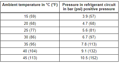
- Temperature of refrigerant circuit components should be equal to ambient temperature. Pressure will deviate from values in table if individual components of refrigerant circuit are warmer or colder.
- At absolute pressure, 0 bar/psi corresponds to absolute vacuum. Normal ambient pressure (positive pressure) corresponds to 1 bar (14.5 psi) absolute pressure. 0 pressure corresponds to an absolute pressure of 1 bar (14.5 psi) on most pressure gauges (indicated by -1 bar (-14.5 psi) below 0).
- For vehicles with High Pressure Sensor -G65-, Refrigerant Circuit Pressure Sensor -G805- or A/C Pressure/Temperature Sensor -G395-, etc. for which measured pressure is displayed in measured value block, pressure measured should coincide. Use the Vehicle Diagnostic Tester ("OBD" or "Guided Fault Finding for the A/C system") and → Heating, Ventilation and Air Conditioning; Rep. Gr.87; System Overview - Refrigerant Circuit (vehicle-specific repair manual).
- Pressure is measured in different units: 1 MPa (145 psi) corresponds to 10 bar (145 psi) positive pressure. 1 bar (14.5 psi) absolute pressure corresponds to 0 bar/psi positive pressure and thus to the ambient pressure (atmospheric pressure).
Pressure in refrigerant circuit lower than indicated in table
Not enough refrigerant in refrigerant circuit
- Determine refrigerant circuit leaks. Refer to → Chapter "Refrigerant Circuit, Determining Leaks ".
- Check the pressure relief valve.
If pressure relief valve has responded:
- Check the coolant fan activation.
- Check the refrigerant lines and hoses for cross-section constrictions caused by inadequate bending radii.
- Check the refrigerant lines and hoses for external damage.
- If no fault is found, clean the refrigerant circuit (flush using refrigerant R134a. Refer to → Chapter "Refrigerant Circuit, Cleaning (Flushing), with Refrigerant R134a"; or blow through using compressed air and nitrogen. Refer to → Chapter "Refrigerant Circuit, Flushing with Compressed Air and Nitrogen").
Pressure in refrigerant circuit in line with table or higher
- Start the engine or activate the ready mode (for example on vehicles with a high-voltage system).
- Set the A/C system to maximum cooling output.
Note
- On vehicles with A/C Compressor Regulator Valve -N280-, the control current can be read in the measured value block. Use the Vehicle Diagnostic Tester (Function "OBD" or "Guided Fault Finding" of the Air Conditioning) and → Heating, Ventilation and Air Conditioning; Rep. Gr.87; A/C Compressor (vehicle-specific repair manual).
- On vehicles with an Electrical A/C Compressor -V470- read out the A/C Compressor Speed Sensor using the different control modules (for example via the respective climate control module or the Thermal Management Control Module -J1024-) using the Vehicle Diagnostic Tester in the "Guided Fault Finding" function.
Vehicles with a Mechanically Driven A/C Compressor
If A/C compressor is not driven with the engine running or regulating valve is not actuated:
- Determine and eliminate cause, for example by checking A/C system DTC memory.
- Observe the test conditions.
- Check the A/C Clutch -N25- voltage supply. If it is OK, repair the A/C clutch.
- Check the A/C Compressor Regulator Valve -87- activation. Use the Vehicle Diagnostic Tester (Function "OBD" or "Guided Fault Finding" of the Air Conditioning) and → Heating, Ventilation and Air Conditioning; Rep. Gr.87; A/C Compressor (vehicle-specific repair manual).
Note
- If the low pressure switch was removed to connect the service station, bridge the electrical connections in the corresponding connector for the pressure measurement.
- A/C compressor is driven by the engine via A/C Clutch -N25-.
- The A/C Compressor Regulator Valve -N280- is activated by the Front A/C Display Control Head -E87- or Climatronic Control Module -J255-. Use the Vehicle Diagnostic Tester (Function "OBD" or "Guided Fault Finding" of the Air Conditioning) and → Heating, Ventilation and Air Conditioning; Rep. Gr.87; System Overview - Refrigerant Circuit (vehicle-specific repair manual).
Vehicles with an Electrical A/C Compressor -V470- (Vehicles with a High-Voltage System)
If the electrical A/C Compressor is not activated while the ready mode is active:
- Check the activation of the A/C compressor via the respective control module. Refer to → Heating, Ventilation and Air Conditioning; Rep. Gr.87; Refrigerant Circuit; System Overview - Refrigerant Circuit and use the Vehicle Diagnostic Tester in the "Guided Fault Finding" function.
All Vehicles
- Checking pressures on vehicles with a restrictor and reservoir (with internally regulated A/C compressor). Refer to → Chapter "Checking Pressures for Vehicles with Restrictor and Reservoir (with Internally Regulated Compressor)".
- Checking pressures on vehicles with an expansion valve and receiver/dryer (with internally regulated A/C compressor). Refer to → Chapter "Checking Pressures on Vehicles with Expansion Valve and Receiver/Dryer (with Internally Regulated Compressor)".
- Checking pressures for vehicles with restrictor, reservoir and A/C Compressor Regulator Valve -N280- (externally regulated A/C compressor). Refer to → Chapter "Vehicles with Restrictor, Reservoir and A/C Compressor Regulator Valve -N280- (Externally Regulated A/C Compressor), Checking Pressures".
- Checking pressures on vehicles with restrictor, receiver/dryer and A/C Compressor Regulator Valve -N280- (externally regulated compressor). Refer to → Chapter "Vehicles with Restrictor, Receiver/Dryer and A/C Compressor Regulator Valve -N280-, Checking Pressures, Externally Regulated Compressor".
- Check the pressures on vehicles with an electrically-driven A/C compressor (Audi A3 e-tron, Audi Q5 hybrid, Audi Q7 e-tron etc.). Refer to → Chapter "Checking Pressures on Vehicles with Electrically Driven A/C Compressor (Vehicles with Hybrid Drive)".
READ NEXT:
 Checking Pressures for Vehicles with Restrictor and Reservoir (with
Internally Regulated Compressor)
Checking Pressures for Vehicles with Restrictor and Reservoir (with
Internally Regulated Compressor)
General Information
Note
Connect the A/C service station. Refer to
→ Chapter "A/C Service Station, Connecting".
Observe the test requirements. Refer to
→ Chapter "Pressures,
Checking Pressures on Vehicles with Expansion Valve and Receiver/Dryer (with
Internally Regulated Compressor)
General Information
Note
Connect the A/C service station. Refer to
→ Chapter "A/C Service Station, Connecting".
Observe the test requirements. Refer to
→ Chapter "Pressures,
Vehicles with Restrictor, Reservoir and A/C Compressor Regulator Valve
-N280- (Externally Regulated A/C Compressor), Checking Pressures
Specified Values for the Refrigerant
Circuit Pressures
Note
Connect the Air Conditioning (A/C) service station. Refer to
→ Chapter "A/C Service Station, Connecting".
Observe the tes
SEE MORE:
Balance Shaft
Overview - Balance Shaft
1 - Cylinder Block
2 - Bolt
Tightening specifications. Refer to
→ Servicing - 4-Cylinder 2.0L 4V TFSI Engine; Rep. Gr.13; Balance Shaft;
Overview - Balance Shaft.
3 - Intake Side Balance Shaft
Removing and installing. Re
Safety belts
General information
Each seat is equipped with a three-point safety
belt. Safety belts that are worn correctly are the
most effective way to reduce the risk of serious or
fatal injuries in a collision. Therefore, wear your
safety belt correctly and make sure that all vehicle
passengers are also wear
