Audi A4: Electrically Driven A/C Compressor, Rinsing (Remove Refrigerant Oil)
Vehicles with a High Voltage System (Hybrid Vehicles)
Extremely Dangerous Due to High-Voltage
The high-voltage system is under high-voltage. Death or serious bodily injury by electric shock.
- Individuals with electronic/medical life- and health sustaining machines in or on their person cannot perform any work on high-voltage systems. Life- and health sustaining machines are for example pain killer pumps, implanted defibrillators, pacemakers, insulin pumps, and hearing aids.
- Have the high-voltage system de-energized by a qualified person.
There is a Risk Of Injury from the Engine Starting Unexpectedly
On electric - hybrid vehicles an active ready mode is difficult to identify. Parts of the body can be clamped or pulled.
- Turn off the ignition.
- Place the ignition key outside of the vehicle interior.
Risk of Damaging the High-Voltage Cables
Misuse can damage the insulation of high-voltage cables or high-voltage connectors.
- Never support objects on the high-voltage cables and the high-voltage connectors.
- Never support tools on the high-voltage cables and the high-voltage connectors.
- Never sharply bend or kink the high-voltage cables.
- When connecting pay attention to the coding of the high-voltage connectors.
- For all procedures on vehicles with high-voltage system pay attention to the additional warning message for these vehicles. Refer to → Chapter "Warnings when Working on Vehicles with High Voltage System".
- If procedures are necessary near components of the high-voltage system "perform a visual inspection of the damage of the high-voltage components and lines". Refer to → Chapter "Performing a Visual Inspection of Damage to High Voltage Components and Cables".
- If work on the components of the high-voltage system is necessity, de-energize the high-voltage system. Refer to → Rep. Gr.93; High-Voltage System, De-Energizing or → Electrical Equipment; Rep. Gr.93; High-Voltage System, De-Energizing.
- Charge the vehicle battery, for example, using the Battery Charger -VAS5904- in the battery support mode to minimize the number of automatic starts during the test- and measuring procedures while the ready mode is active. Refer to → Electrical Equipment General Information; Rep. Gr.27; Battery; Charging the Battery and → Electrical Equipment; Rep. Gr.93; General Notes for Working on the High Voltage System.
- Move the selector level into position "P", activate the parking brake and arrange the necessary tools for testing and measuring procedures that require the ready mode to be active or that require the ignition to be on, so that they cannot come into contact with the turning components in the engine and so that they are not in the vicinity of the turning components of a running engine.
 Note
Note
- Also move the selector lever into position "P" and activate the parking brake for testing and measuring procedures which require the ignition to be on, but do not require the ready mode to be active.
- The ready mode is displayed in the Instrument Cluster Control Module -J285- above the "powermeter". Refer to Owner's Manual.
- Activate and deactivate the ready mode. Refer to Owner's Manual (consult the display in the Instrument Cluster Control Module -J285-).
General notes to remove the refrigerant oil from the electrically driven A/C compressor (by flushing).
Note
- Electrically driven A/C compressors cannot have the refrigerant oil poured out in the same manner as a mechanically driven A/C compressor. There is no drain plug and because it is installed inside defending on the version only a specialized part or no refrigerant oil can be poured out. Depending on the version and the storage of the A/C compressor there remains when pouring our approximately 30 to 80 cm 3 refrigerant oil in the A/C compressor (the electrically driven A/C compressor cannot be turned). For this reason, the A/C compressor is to be flushed to remove the refrigerant oil and to determine the amount of refrigerant oil in the A/C compressor, depending on the complaint. Refer to → Chapter "Compressor, Replacing without the Need for Flushing Refrigerant Circuit".
- The refrigerant oil can be removed by flushing in the flow direction for electrically driven A/C compressors (because of the installed valve it is not possible to flush against the flow direction).
- To flush, arrange the A/C compressor so that the connection for the refrigerant line on the high pressure side is as low as possible.
- The electrically driven A/C compressor is to be flushed when, there is dirt, too much refrigerant oil is in the refrigerant circuit, or is contaminated (with moisture debris) and to remove refrigerant oil from the A/C compressor. In these cases the refrigerant circuit must also be flushed, so that it will be cleaned and the correct refrigerant oil quantity for the refrigerant circuit can be set. Refer to → Chapter "Refrigerant Oil Capacities".
- If the electrically driven A/C compressor is replaced, it is not always necessary to flush the coolant circuit. The amount of refrigerant oil found in the removed A/C compressor can be removed by flushing the A/C compressor. Pour the refrigerant oil out of the new A/C compressor so that only the amount remains (plus 10 cm 3) as before the old A/C compressor was flushed out. Refer to → Chapter "Compressor, Replacing without the Need for Flushing Refrigerant Circuit".
- To remove the refrigerant oil from the removed A/C compressor the refrigerant oil must be flushed from the replaced A/C compressors and the removed about measured (Empty the used oil collection from the A/C service station before flushing). Pour the refrigerant oil out of the new A/C compressor so that only the amount or refrigerant oil remains (plus 10 cm 3) in the new A/C compressor as the amount of flushed out refrigerant oil from the old A/C compressor. Dispose of the refrigerant oil removed from the defective and the new A/C compressor and poured out refrigerant oil from the new A/C compressor.
- In not enough refrigerant oil can be poured out from the A/C compressor to be installed, flush the new A/C compressor. Fill the A/C compressor to be installed in after flushing with as much new refrigerant oil as was flushed from the removed A/C compressor. Example: from the removed A/C compressor 120 cm 3 refrigerant oil removed in the new A/C compressor to be installed there are 200 cm 3. Refer to the data plate and → Chapter "Refrigerant Oil Capacities". Then from the A/C compressor to be installed 110 cm 3 (120 cm 3 minus 10 cm 3) must be poured out so that the refrigerant oil quantity in the refrigerant circuit after installing is correct. If the required amount of refrigerant oil cannot be poured out, flush the A/C compressor to be installed. In the new A/C compressor as much refrigerant oil is to be filled as was flushed out of the old A/C compressor.
Flush the Electrically Driven A/C Compressor
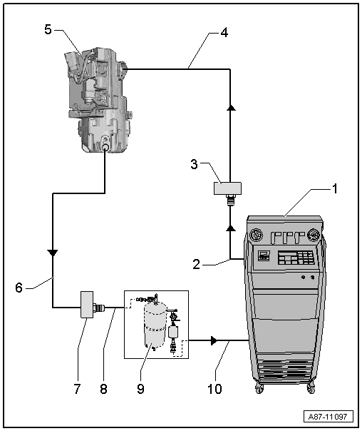
1 - A/C Service Station
- With electronics and a flushing program, A/C Service Station With Flushing Device. Refer to the Parts Catalog (Tools; Special Tools and Equipment: A/C and Heating).
- If an A/C service station without a flushing program is used, the procedure must be performed manually (evacuate, flush three times with at least 2 kg refrigerant each and extract refrigerant again, evacuate).
2 - A/C Service Station Refrigerant Hose
- From high pressure side of A/C service station (mostly colored red) to low pressure side connection of A/C compressor on refrigerant circuit (larger diameter).
3 - Adapter to the Connection for the Low Pressure Side on the A/C Compressor
- There are different versions depending on vehicle. Refer to → Chapter "Adapter for Assembling Flushing Circuit".
- Use the adapter from the Refrigerant Circuits Adapter Set 1 -VAS6338/1- (here the Refrigerant Circuits Adapter Set 2 - Adapter 41 -VAS6338/41-).
4 - Refrigerant Line
- To the A/C compressor connection on the adapter. Refer to -item 3- → Item
Note
- Only use the refrigerant line when the Refrigerant Circuits Adapter Set 2 - Adapter 41 -VAS6338/41- is not available.
- If the Refrigerant Circuits Adapter Set 2 - Adapter 41 -VAS6338/41- is not available to remove the flushing circuit, for example remove the refrigerant lines to the condenser, from the vehicle (or use a refrigerant line with the part number 7L6 820 744 AD). Refer to the Parts Catalog).
5 - Electrically-Driven A/C Compressor
- The A/C compressor is flushed in the flow direction (from the low pressure side input to the high pressure side output)
- So that as much refrigerant oil as possible is flushed out from the A/C compressor, the A/C compressor must be positioned so that the high pressure side output is as low as possible
6 - Refrigerant Line
- To the A/C compressor connection on the adapter. Refer to -item 7- → Item
Note
- Only use the refrigerant line when the Refrigerant Circuits Adapter Set 2 - Adapter 40 -VAS6338/40- is not available.
- If the Refrigerant Circuits Adapter Set 2 - Adapter 40 -VAS6338/40- is not available to remove the flushing circuit use for example on a refrigerant line with the part number 7L6 820 721 BF or 4G0 260 701 AB. Refer to the Parts Catalog.
7 - Adapter to the Connection for the High Pressure Side on the Refrigerant Circuit
- There are different versions depending on vehicle. Refer to → Chapter "Adapter for Assembling Flushing Circuit".
- Use the adapter from the Refrigerant Circuits Adapter Set 1 -VAS6338/1- (here the Refrigerant Circuits Adapter Set 2 - Adapter 40 -VAS6338/40-).
8 - Charge Hose for Refrigerant Circuit Flushing Device
- From connection to the high pressure side of the A/C compressor on the refrigerant circuit (smaller diameter) to input of refrigerant circuit flushing device.
9 - Flushing Equipment for Refrigerant Circuits
- There are different versions of the Refrigerant Circuit Flushing Device. Refer to the Parts Catalog (Tools; Special Tools and Equipment: A/C and Heating).
- With filter, viewing glass, safety valve, heating, refrigerant container etc. (depending on version).
- Depending on the construction of the A/C service station and of refrigerant circuit flushing device, a check-valve may be installed at output of refrigerant circuit flushing device (to guarantee correct direction of refrigerant flow during flushing).
10 - A/C Service Station Refrigerant Hose
- From the low pressure side of the service station (mostly blue) to the output of the flushing device for refrigerant circuits.
READ NEXT:
 Adapter for Assembling Flushing Circuit
Various adapters which are required to connect the Air
Conditioning (A/C) service station to the refrigerant circuit
for flushing and to bridge the removed receiver/dryer or
reservoir and expansi
General Information
Vehicles with a High Voltage System (Hybrid Vehicles)
Extremely Dangerous Due to High-Voltage
The high-voltage system is under high-voltage. Death or serious
bodily injury by electric shock.
- I
SEE MORE:
Compressor, Replacing on Account of Leakage or Internal Damage
Vehicles with a High Voltage System (Hybrid Vehicles)
Extremely Dangerous Due to High-Voltage
The high-voltage system is under high-voltage. Death or serious
bodily injury by electric shock.
- Individuals with electronic/medical life- and health sustaining
machines in or on their person canno
Right and Left Multifunction Buttons on Steering Wheel -E441-/-E440-,
Removing and Installing
Right and Left Multifunction Buttons on Steering Wheel -E441-/-E440-,
Removing and Installing, Steering Wheel with Round Airbag
Special tools and workshop equipment required
Trim Removal Wedge -3409-
The multifunction buttons -2-
are clipped to the decorative trim -1-.
The decorative trim -1-
