Audi A4: Overview - Infotainment System
Overview - Infotainment System, MMI Radio Plus, 18E
- Information Electronics Control Module 1 -J794- with integrated CD player/SD card reader in the glove compartment
- Multimedia System Control Head -E380- in the center console, UJ0
- Front Information Display Control Head -J685-, display in center of the instrument panel
- External Audio Source Connection -R199- (USB Charging, AUX IN) in the center console storage compartment, UE4
- Sound systems: basic/standard (8RM/9VD)
- The Radio -R- is integrated in the Information Electronics Control Module 1 -J794-
- Bluetooth Hands-Free Calling, 9ZX
Optional
- Digital Radio -R147- integrated in the Information Electronics Control Module 1 -J794-, only ER1/ER2 and QV3
- Radio System, Satellite -R146- integrated in the Information Electronics Control Module 1 -J794-, only ER3 and QV3
- Digital Sound System Control Module -J525- in the left rear of the luggage compartment, only 9VS
- Instrument Cluster Control Module -J285-, instrument cluster display, 9S7
- Premium Sound System, Bang & Olufsen, 9VS
- External Audio Source Connection -R199- (USB quantity 2, Aux IN) in the center console storage compartment, UE7
- Audi phone box, 9ZE
- Multifunction Steering Wheel
Fault Finding is performed using the "Guided Fault Finding" on the Vehicle Diagnostic Tester.
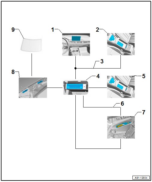
1 - Front Information Display Control Head -J685-, Display in Center of the Instrument Panel
2 - Multimedia System Control Head -E380- in the Center Console
3 - CAN Bus, MMI
4 - Information Electronics Control Module 1 -J794- in the Glove Compartment
5 - External Audio Source Connection -R199- in the Center Console Storage Compartment
6 - MOST Bus
7 - Digital Sound System Control Module -J525- in Luggage Compartment on Left Rear Side
8 - Antenna Amplifier
9 - Rear Window Antennas
The MOST Bus performs the system data exchange in the CAN Bus and MMI.
Fault Finding is performed using the "Guided Fault Finding" on the Vehicle Diagnostic Tester.
Notes on MOST Bus
The optical data bus "MOST Bus" is used in addition to the CAN Bus.
A fiber-optic cable is used. Fiber optic cables are routed inside corrugated tubes for protection.
Replace the complete fiber-optic cable if possible.
The front surface of the connectors must not be contaminated.
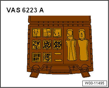
If disconnecting the connectors: Attach the Fiber-Optic Repair Set - Connector Protective Caps -VAS6223/9-.
When routing fiber-optic cables, make sure not to go below the minimum bending radius of 25 mm. Do not crush or kink fiber optic cables.
Repairing fiber-optic cables. Refer to → Chapter "General Repair Information".
Overview - Infotainment System, MMI Navigation, I8S
- Information Electronics Control Module 1 -J794- with integrated CD player/SD memory card reader/navigation system in the glove compartment, 7UF
- Multimedia System Control Head -E380- in the center console, UJ0
- Front Information Display Control Head -J685-, display in center of the instrument panel
- External Audio Source Connection -R199- in the center console storage compartment, UE4
- Sound system: Standard/Bang & Olufsen, 9VD/9VS
- Digital Sound System Control Module -J525- in the left rear of the luggage compartment, only 9VS
- Radio -R- integrated in the Information Electronics Control Module 1 -J794-, I8S
- Bluetooth Hands-Free Calling, 9ZX
- Voice recognition system, QH1
Optional
- Digital Radio -R147- integrated in the Information Electronics Control Module 1 -J794-, only ER1/ER2 and QV3
- Radio System, Satellite -R146- integrated in the Information Electronics Control Module 1 -J794-, only ER3 and QV3
- External Audio Source Connection -R199- (USB quantity 2, Aux IN) in the center console storage compartment, UI2/UE7
- Instrument Cluster Control Module -J285-, instrument cluster display, 9S7
- Audi phone box, 9ZE
- Audi phone box connect, 9ZE/EL3
- Multifunction Steering Wheel
ASI - Audi Smartphone Integration
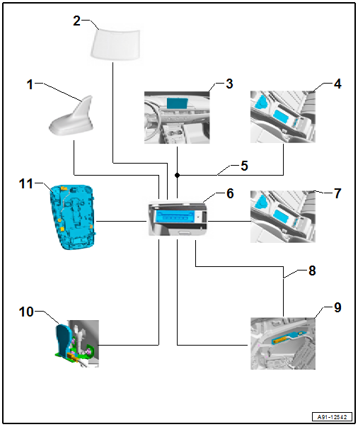
1 - Roof Antenna -R216-
2 - Rear Window Antenna with Antenna Amplifier
3 - Front Information Display Control Head -J685-, Display in Center of the Instrument Panel
4 - Multimedia System Control Head -E380- in the Center Console
5 - CAN Bus, MMI
6 - Information Electronics Control Module 1 -J794- in the Glove Compartment
7 - External Audio Source Connection -R199- in the Center Console Storage Compartment
8 - MOST Bus
9 - Digital Sound System Control Module -J525- in Luggage Compartment on Left rear Side
10 - Bumper Antennas
11 - Microphone Unit in Front Roof Module - R164- in the Front Interior Lamp -W1-
The MOST Bus performs the system data exchange in the CAN Bus and MMI.
Fault Finding is performed using the "Guided Fault Finding" on the Vehicle Diagnostic Tester.
Notes on MOST Bus
The optical data bus "MOST Bus" is used in addition to the CAN Bus.
A fiber-optic cable is used. Fiber optic cables are routed inside corrugated tubes for protection.
Replace the complete fiber-optic cable if possible.
The front surface of the connectors must not be contaminated.
If disconnecting the connectors: Attach the Fiber-Optic Repair Set - Connector Protective Caps -VAS6223/9-.
When routing fiber-optic cables, make sure not to go below the minimum bending radius of 25 mm. Do not crush or kink fiber optic cables.
Repairing fiber-optic cables. Refer to → Chapter "General Repair Information".
Overview - Infotainment System, MMI Navigation Plus, I8H
- Information Electronics Control Module 1 -J794- with integrated DVD player/SD memory card reader/navigation system/HDD in the glove compartment, 7UG
- Multimedia System Control Head -E380- MMI touch in the center console, UJ1
- Front Information Display Control Head -J685-, display in center of the instrument panel
- Instrument Cluster Control Module -J285-, instrument cluster display, 9S7
- External Audio Source Connection -R199- (USB Charging, AUX IN) in the center console storage compartment, UE4/UE7
- Sound systems: basic/standard (8RM/9VD)
- The Radio -R- is integrated in the Information Electronics Control Module 1 -J794-
- Bluetooth Hands-Free Calling, 9ZX
- Voice recognition system, QH1
Optional
- Digital Radio -R147- integrated in the Information Electronics Control Module 1 -J794-, only ER1/ER2 and QV3
- Radio System, Satellite -R146- integrated in the Information Electronics Control Module 1 -J794-, only ER3 and QV3
- Digital Sound System Control Module -J525- in the left rear of the luggage compartment, only 9VS
- Instrument Cluster Control Module -J285-, instrument cluster display, 9S8
- External Audio Source Connection -R199- (USB quantity 2, Aux IN) in the center console storage compartment, UI2/UE7
- TV Tuner -R78- in the right rear of the luggage compartment, QU1/QV1
- Premium Sound System, Bang & Olufsen, 9VS
- Audi phone box, 9ZE
- Audi phone box connect, 9ZE/EL3
- Multifunction Steering Wheel
ASI - Audi Smartphone Integration
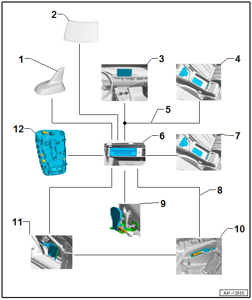
1 - Roof Antenna -R216-
2 - Rear Window Antenna with Antenna Amplifier
3 - Front Information Display Control Head -J685-, Display in Center of the Instrument Panel
4 - Multimedia System Control Head -E380- in the Center Console
5 - CAN Bus, MMI
6 - Information Electronics Control Module 1 -J794- in the Glove Compartment
7 - Telephone Baseplate -R126-/External Audio Source Connection -R199- in the Center Console Storage Compartment
8 - MOST Bus
9 - Bumper Antennas
10 - Digital Sound System Control Module -J525- in Luggage Compartment on Left Rear Side
11 - TV Tuner -R78- in Luggage Compartment on Rear Right Side
12 - Microphone Unit in Front Roof Module -R164- in the Front Interior Lamp -W1-
The MOST Bus performs the system data exchange in the CAN Bus and MMI.
Fault Finding is performed using the "Guided Fault Finding" on the Vehicle Diagnostic Tester.
Notes on MOST Bus
The optical data bus "MOST Bus" is used in addition to the CAN Bus.
A fiber-optic cable is used. Fiber optic cables are routed inside corrugated tubes for protection.
Replace the complete fiber-optic cable if possible.
The front surface of the connectors must not be contaminated.
If disconnecting the connectors: Attach the Fiber-Optic Repair Set - Connector Protective Caps -VAS6223/9-.
When routing fiber-optic cables, make sure not to go below the minimum bending radius of 25 mm. Do not crush or kink fiber optic cables.
Repairing fiber-optic cables. Refer to → Chapter "General Repair Information".
READ NEXT:
 Component Location Overview - Infotainment System
1 - Bracket
2 - Information Electronics Control Module 1 -J794-
Connector assignment. Refer to
→ Wiring diagrams, Troubleshooting & Component locations.
Removing an
Multimedia System Control Head -E380-, Removing and Installing
Multimedia System Control Head -E380-, Removing and Installing, Manual
Transmission
The Multimedia System Control Head -E380- is located in the
center console.
Removing
- Turn off the ignition
SEE MORE:
Efficiency assist
Description
Applies to: vehicles with efficiency assist
Efficiency assist can assist the driver with predictive
information in order to reduce fuel consumption.
Depending on vehicle equipment, the system
may access data from the navigation system,
the camera behind the windshield, and the radar
s
Settings
Telephone settings
Applies to: vehicles with telephone
Applies to: MMI: Select on the home screen:
PHONE > .
The following options may be possible, depending
on your mobile device:
Decline with text message
Edit voicemail number
Switching between two mobile devices
Requirement: phone 1 an
