Audi A4: Turbocharger, G-Charger
Turbocharger
All procedures and components are described under: → Servicing - 4-Cylinder 2.0L 4V TFSI Engine; Rep. Gr.21; Turbocharger; Turbocharger, Removing and Installing.
Charge Air System
Overview - Charge Air System
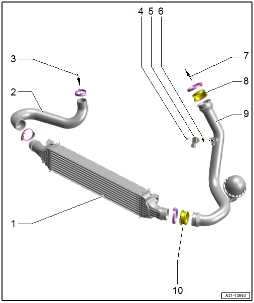
1 - Charge Air Cooler
- Removing and installing. Refer to → Chapter "Charge Air Cooler, Removing and Installing".
- If there are small impressions on the slats, refer to → Servicing - 4-Cylinder 2.0L 4V TFSI Engine; Rep. Gr.00; Repair Information; Radiator and Condenser Assembly.
2 - Air Duct Hose
- Must be free of oil and grease before installing
3 - From the Turbocharger
4 - Bolt
- 7 Nm
- Repair solution for broken catch
- Thread cutting
- Position the bolt by hand and tighten it until it finds the old threads. Then tighten the bolt to the specification.
5 - Charge Air Pressure Sensor -G31-
- Removing and installing. Refer to → Chapter "Charge Air Pressure Sensor -G31-, Removing and Installing".
6 - O-ring
- Replace after removing
7 - To Intake Manifold
8 - Air Duct Pipe
- Must be free of oil and grease before installing
9 - Pipe
10 - Seal
- Replace if damaged
Overview - Charge Air Hose Connections
All components are described under: → Servicing - 4-Cylinder 2.0L 4V TFSI Engine; Rep. Gr.21; Charge Air System; Overview - Charge Air Hose Connections.
Charge Air Cooler, Removing and Installing
 Caution
This procedure contains mandatory replaceable parts. Refer to component overview and parts catalog prior to starting procedure.
Mandatory Replacement Parts
- Seal - Pipe to Charge Air Cooler
Removing
 Note
Note
Pay attention to the guidelines for clean working conditions. Refer to → Servicing - 4-Cylinder 2.0L 4V TFSI Engine; Rep. Gr.00; Repair Information; Guidelines for Clean Working Conditions.
- Remove the lock carrier cover and right and left air intake grille as well as the bumper cover end plate. Refer to → Body Exterior; Rep. Gr.63; Front Bumper; Attachment, Removing and Installing.
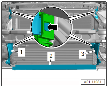
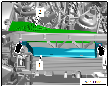
- Release the catches -arrow- and remove the air ducts -1 and 3-.
Note
Ignore item -2-.
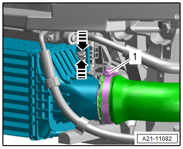
- Loosen the left and right hose clamp -1- and remove the air duct pipe from the charge air cooler.
Caution
Risk of destroying the charge air cooler.
If the catches are damaged, the charge air cooler must be replaced.
- Release the retainers in the direction of -arrows- on the left and right sides and disengage the charge air cooler from the radiator.
- Remove the charge air cooler downward.
Installing
Install in reverse order of removal and note the following:
Note
- If there are small impressions on the slats. Refer to → Servicing - 4-Cylinder 2.0L 4V TFSI Engine; Rep. Gr.00; Repair Information; Radiator and Condenser Assembly.
- Secure all hose connections with hose clamps that match the ones used in series production. Refer to the Parts Catalog.
- Install the lock carrier cover and right and left air intake grille as well as the bumper cover end plate. Refer to → Body Exterior; Rep. Gr.63; Front Bumper; Attachment, Removing and Installing.
Tightening Specifications
- Refer to → Servicing - 4-Cylinder 2.0L 4V TFSI Engine; Rep. Gr.21; Charge Air System; Overview - Charge Air Hose Connections.
Charge Air Pressure Sensor -G31-, Removing and Installing
Removing
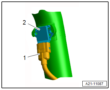
- Disconnect the connector -1-.
- Turn the Charge Air Pressure Sensor -G31--2- counter-clockwise and remove from the air duct pipe.
Installing
Install in reverse order of removal and note the following:
- Bring the Charge Air Pressure Sensor -G31- into the installation position and turn clockwise until it engages.
Note
- Replace the O-ring after removing.
- If the catch on the air duct pipe is broken secure the Charge Air Pressure Sensor -G31- with two bolts. Refer to the Parts Catalog.
Tightening Specifications
- Refer to → Chapter "Overview - Charge Air System"
Charge Air System, Checking for Leaks
Special tools and workshop equipment required
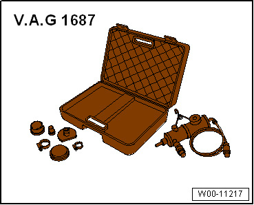
- Turbo System Tester Kit -VAG1687- with Turbo System Tester Kit - Adapter 6 -VAG1687/6- and Turbo System Tester Kit - Adapters -VAG1687/3-, -1687/10-, Turbo System Tester Kit - Adapter 11 -VAG1687/11-, Turbo System Tester Kit - Adapter 12 -VAG1687/12-, Turbo System Tester Kit - Adapter 13-2 -VAG1687/13-2-, Turbo System Tester Kit - Adapter -VAG1687/15-.
- Ultrasonic Tester -VAG1842-
Procedure
Note
Pay attention to the guidelines for clean working conditions. Refer to → Servicing - 4-Cylinder 2.0L 4V TFSI Engine; Rep. Gr.00; Repair Information; Guidelines for Clean Working Conditions.
- Remove the engine cover. Refer to → Servicing - 4-Cylinder 2.0L 4V TFSI Engine; Rep. Gr.10; Engine Cover; Engine Cover, Removing and Installing.
- Remove the lock carrier cover. Refer to → Body Exterior; Rep. Gr.63; Front Bumper; Attachments, Removing and Installing.
- Remove the bolts -arrows- and the air guide -2-.
Note
Ignore item -1-.
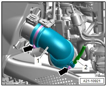
- Loosen the hose clamps -arrows-.
- Remove the vacuum hose -2- and air duct pipe -1-.
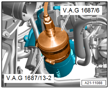
- Install the -VAG1687/6- and -VAG1687/13-2- on the turbocharger.
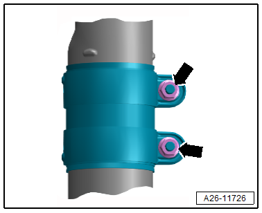
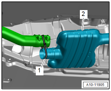
- Loosen the front clamping sleeve -arrows- and push toward the rear.
Caution
Risk of damaging the couplings in the front muffler.
Do not bend couplings in front muffler more than 10º.
- Slightly lower the front muffler -2- and secure as shown with a cable tie -1-.
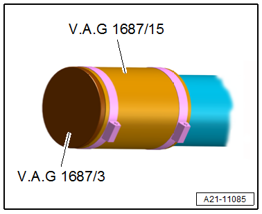
- Seal the front muffler with -VAG1687/3- and -VAG1687/15-.
- Connect the -VAG1687- with the connection -5- on the -VAG1687/6-.
Prepare the -VAG1687- as follows:
- Completely remove the pressure regulating valve -2- and close the valves -3 and 4-.
- Pull the knob in order to rotate the pressure regulating valve -2-.
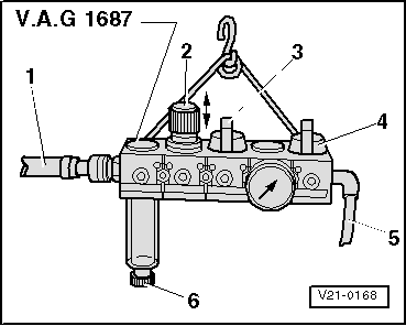
- Connect the -VAG1687- to compressed air -1- with a commercially available intermediate piece.
Note
If there is water in the viewing glass, drain it through the water drain plug -6-.
- Open the valve -3-.
Caution
There is a risk of damage if the pressure is set too high.
The pressure must not exceed 0.5 bar (7.2 psi)!
- Set the pressure to 0.5 bar (7.2 psi) using the pressure regulating valve -2-.
- Open the valve -4- and wait until the test circuit is filled. Regulate the pressure to 0.5 bar (7.2 psi) again if required.
- Listen, feel and use commercially available leak detection spray or the -VAG1842- to check the charge air system for leaks.
Note
- A small quantity of air dissipates via the valves in the engine. For this reason a pressure retention test is not possible.
- Refer to the Operating Instructions for information on using the -VAG1842-.
- Release the pressure in the test circuit by pulling off the coupling before removing the adapter.
- Secure all hose connections with hose clamps that match the ones used in series production. Refer to the Parts Catalog.
Assembling
Assemble in the reverse order of removal. Note the following:
- Install the lock carrier cover. Refer to → Body Exterior; Rep. Gr.63; Front Bumper; Attachments, Removing and Installing.
- Install the engine cover. Refer to → Servicing - 4-Cylinder 2.0L 4V TFSI Engine; Rep. Gr.10; Engine Cover; Engine Cover, Removing and Installing.
Tightening Specifications
- Refer to → Chapter "Overview - Air Filter Housing"
- Refer to → Chapter "Overview - Muffler"
- Refer to → Servicing - 4-Cylinder 2.0L 4V TFSI Engine; Rep. Gr.21; Charge Air System; Overview - Charge Air Hose Connections.
Special Tools
Special tools and workshop equipment required
- Turbo System Tester Kit -VAG1687- with Turbo System Tester Kit - Adapter 6 -VAG1687/6- and Turbo System Tester Kit - Adapters -VAG1687/3-, -1687/10-, Turbo System Tester Kit - Adapter 11 -VAG1687/11-, Turbo System Tester Kit - Adapter 12 -VAG1687/12-, Turbo System Tester Kit - Adapter 13-2 -VAG1687/13-2-, Turbo System Tester Kit - Adapter -VAG1687/15-.
- Ultrasonic Tester -VAG1842-
READ NEXT:
 Injection System
Component Location Overview - Injection System
Component Location Overview - Engine Compartment
1 - Oxygen Sensor after Catalytic Converter -G130- with Heater for
Oxygen Sensor 1 after Cat
Air Filter
Overview - Air Filter Housing
1 - Snow Screen
Market-Specific Version
2 - Air Duct
On the lock carrier
Clean off any salt and dirt
3 - Water Drain
Clean
4
SEE MORE:
Rear Axle Camber, Adjusting
Caution
This procedure contains mandatory replaceable parts.
Refer to component overview and parts catalog prior to
starting procedure.
Mandatory Replacement Parts
Nut - for Adjusting Bolt
Procedure
- Remove the nut -1- from the
subframe/rear lower transverse link threaded connec
Finishing
Reinstall any covers on the wheel bolts that
were removed.
Store the vehicle tool kit in its designated
place.
If the removed wheel does not fit in the spare
wheel well, store it securely in the luggage
compartment.
Check the tire pressure on the installed wheel
as soon as possible.
Corre
