Audi A4: Airbag Control Module
Overview - Airbag Control Module
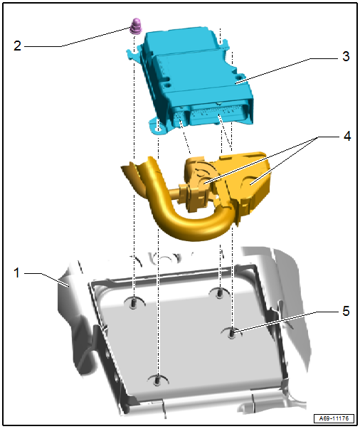
1 - Center Tunnel
2 - Nut
- 9 Nm
- Quantity: 4
- The thread must be paint and contaminant free, nut and ground pins serve as ground connection for the control module.
3 - Airbag Control Module -J234-
- Removing and installing. Refer to → Chapter "Airbag Control Module -J234-, Removing and Installing".
- The control module is grounded via the housing with the body.
4 - Connectors
5 - Threaded Pins
- Quantity: 4
- The thread must be paint and contaminant free, nut and ground pins serve as ground connection for the control module.
Airbag Control Module -J234-, Removing and Installing
Special tools and workshop equipment required
- Vehicle Diagnostic Tester
- Pry Lever -80-200-
- Scissors
Removing
 WARNING
Risk of injury due to involuntary deployment.
Pay attention to the safety precautions when working with pyrotechnic components. Refer to → Chapter "Safety Precautions when Working with Pyrotechnic Components".
- Disconnect the battery ground cable with the ignition turned on. Refer to → Electrical Equipment; Rep. Gr.27; Battery; Battery, Disconnecting and Connecting.
- Remove the center console. Refer to → Chapter "Center Console, Removing and Installing".
- Remove the Access/Start System Antenna 1 in Vehicle Interior -R138-. Refer to → Electrical Equipment; Rep. Gr.94; Access/Start Authorization; Component Location Overview - Keyless Access Authorization System.
- Equipped on some models: Remove the rear air duct. Refer to → Heating, Ventilation and Air Conditioning; Rep. Gr.87; Air Routing; Overview - Air Routing and Air Distribution in Vehicle Interior.
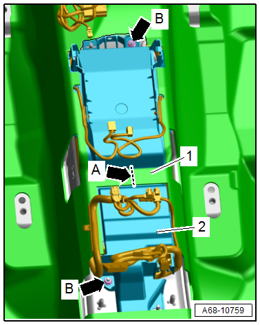
- Cut through the carpet connecting piece -1- at the position shown in the illustration -arrow A- using scissors.
- Remove the nut -arrows B-.
- Unclip the control module cover -2- from the threaded pin.
- Unclip the wiring harness from the cover using the Pry Lever -80-200- and free it up.
- Pull the control module cover out from under the carpet and remove it.
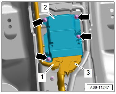
- Remove the nuts -arrows-.
WARNING
Risk of injury due to involuntary deployment.
Before handling pyrotechnic components (For example, disconnecting the connector), the person handling it must "discharge static electricity". For example, this can be done by briefly touching the door striker.
- Remove the airbag control module -2- from the threaded pin.
- Disconnect the connectors -1 and 3- by releasing the connector safety catch and opening the securing clip on the connector.
Installing
WARNING
Risk of injury due to involuntary deployment.
- Pay attention to the safety precautions when working with pyrotechnic components. Refer to → Chapter "Safety Precautions when Working with Pyrotechnic Components".
- Before handling pyrotechnic components (For example, connecting a connector), the person handling it must "discharge static electricity". For example, this can be done by briefly touching the door striker.
Install in reverse order of removal and note the following:
 Note
Note
Make sure the connectors are pushed in all the way and that they engage audibly.
WARNING
Repairing pyrotechnic components (For example the airbag and seat belt tensioner) incorrectly increases the risk of injuries due to unintentional deployments when the battery is connected.
- The ignition must be on when connecting the battery.
- There must not be anyone in the vehicle interior when connecting the battery.
- Connect the battery ground cable with the ignition switched on. Refer to → Electrical Equipment; Rep. Gr.27; Battery; Battery, Disconnecting and Connecting.
WARNING
Risk of malfunction.
- After every removal and installation of the Airbag Control Module -J234-, the Guided Function "Inertial sensor basic setting" must be performed.
- If the Airbag Control Module -J234- is replaced with a new part, the basic setting is performed when implementing the "15 - Replace airbag control module" program.
- If the Airbag Control Module -J234- is removed and then the same one is reinstalled, perform the "inertial sensor basic setting" as follows:
- Connect the Vehicle Diagnostic Tester.
- Switch the ignition on.
- Select and start the Diagnostic operating mode.
- Select the Test plan tab.
- Select the Select individual test button and select the following tree structure consecutively:
- Body
- Body Assembly
- 01 - OBD-capable systems
- 15 - Airbag - Airbag Control Module -J234-
- 15 - Airbag, Functions
- 15 - Basic Setting
- 15 - Inertial Sensor Basic Setting
- Start the selected program and follow the instructions on the Vehicle Diagnostic Tester display.
Note
If the Airbag Indicator Lamp -K75- indicates a fault after installing, check the DTC memory, erase it and check it again using the Vehicle Diagnostic Tester.
Installation instructions: tightening specifications, replacing body parts. Refer to → Chapter "Overview - Airbag Control Module" and → Chapter "Overview - Center Console, Storage Compartment".
READ NEXT:
 Battery Interrupt Igniter
Overview - Battery Interrupt Igniter
1 - Connector
For the Battery Interrupt Igniter -N253-
2 - Nuts
Tightening specification. Refer to
→ Electrical Equipment; R
Driver Side Airbag
Overview - Driver Side Airbag
1 - Wiring Harness
For Driver Airbag Igniter -N95- and Driver Airbag Release Valve Igniter
-N490-
Replacing. Refer to
→ Chapter "Airbag Connector,
Front Passenger Airbag
Overview - Front Passenger Airbag
1 - Connector
For Front Passenger Airbag Igniter 2 -N132-
2 - Connector
For Front Passenger Airbag Release Valve Igniter -N491-
3 -&nb
SEE MORE:
A/C Pressure Switch -F129-
Note
Switch pressures, removing and installing switches as well
as switch arrangement and version. Refer to vehicle specific
refrigerant circuit
→ Heating, Ventilation and Air Conditioning; Rep. Gr.87; System
Overview - Refrigerant Circuit (vehicle-specific
repair manua
Wiring Harnesses, Repairing
Note
Observe general notes for repairs on the vehicle electrical
system. Refer to
→ Chapter "Vehicle Electrical System, General Repair
Information".
Airbag and Belt Tensioner Wires, Repairing
In addition to the general repairs on wiring harnesses, the
following methods and instruc
