Audi A4: Battery Interrupt Igniter
Audi A4 (B9) 2016-2026 Service Manual / Body / Body Interior / Passenger Protection, Airbags, Seat Belts / Battery Interrupt Igniter
Overview - Battery Interrupt Igniter
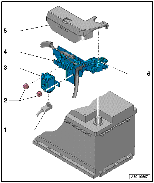
1 - Connector
- For the Battery Interrupt Igniter -N253-
2 - Nuts
- Tightening specification. Refer to → Electrical Equipment; Rep. Gr.97; Relay Panels, Fuse Panels, E-Boxes; Component Location Overview - Relay Panels, Fuse Panels, E-Boxes.
3 - Battery Interrupt Igniter -N253-
- Available only together with -4-
4 - Main Fuse Panel to Battery
- Removing and installing. Refer to → Electrical Equipment; Rep. Gr.97; Relay Panels, Fuse Panels, E-Boxes; Component Location Overview - Relay Panels, Fuse Panels, E-Boxes.
5 - Cover
- For the main fuse panel
6 - Positive Terminal Clamp
- Tightening specification. Refer to → Electrical Equipment; Rep. Gr.27; Battery; Overview - Battery.
Battery Interrupt Igniter, Removing and Installing
 WARNING
Risk of injury due to involuntary deployment.
- Pay attention to the safety precautions when working with pyrotechnic components. Refer to → Chapter "Safety Precautions when Working with Pyrotechnic Components".
- Observe the disposal regulations for pyrotechnical components. Refer to → Chapter "Airbag, Belt Tensioner and Battery Cut-Out Units, Storing, Transporting and Disposing (Pyrotechnic Components)".
 Note
Note
- If the Airbag Indicator Lamp -K75- turns on after a collision, check whether crash data is stored using the Vehicle Diagnostic Tester. If this is the case, check if the malfunction "Resistance too high" for the Battery Interrupt Igniter -N253- is stored in the DTC memory. If this is the case, the Battery Interrupt Igniter -N253- must be replaced.
- The Battery Interrupt Igniter -N253- interrupts the electrical circuit each time an airbag is deployed. The Battery Interrupt Igniter -N253- must be replaced after a deployment.
- The Battery Interrupt Igniter -N253- is only available as a replacement part with the main fuse panel on the battery.
Main fuse panel on battery, removing and installing. Refer to → Electrical Equipment; Rep. Gr.97; Relay Panels, Fuse Panels, E-Boxes; Component Location Overview - Relay Panels, Fuse Panels, E-Boxes.
READ NEXT:
 Driver Side Airbag
Overview - Driver Side Airbag
1 - Wiring Harness
For Driver Airbag Igniter -N95- and Driver Airbag Release Valve Igniter
-N490-
Replacing. Refer to
→ Chapter "Airbag Connector,
Front Passenger Airbag
Overview - Front Passenger Airbag
1 - Connector
For Front Passenger Airbag Igniter 2 -N132-
2 - Connector
For Front Passenger Airbag Release Valve Igniter -N491-
3 -&nb
Thorax Airbags
Overview - Front Thorax Airbag
1 - Front Thorax Airbag
With
Driver Thorax Airbag Igniter -N199-
Front Passenger Thorax Airbag Igniter -N200-
WARNING
Risk of injury due to in
SEE MORE:
Door Arrester, Removing and Installing
Removing
- Move the door window into the "closed" position.
- Remove the door trim panel. Refer to
→ Body Interior; Rep. Gr.70; Front Door Trim Panels; Front Door
Trim Panel, Removing and Installing.
- Remove the speaker. Refer to
→ Communication; Rep.
Locking Mechanism Trim, Removing and Installing
Special tools and workshop equipment required
Trim Removal Wedge -3409-
Removing
- Unlock the rear seat backrest.
- Make sure the button -2-
(indicator) is in the "up" position.
- Push the tabs in the direction of -arrows-
on both sides of the trim using a -3409-.
- Remove t
© 2019-2026 Copyright www.audia4b9.com
