Audi A4: Wiring Harnesses, Repairing
Audi A4 (B9) 2016-2026 Service Manual / Electrical System / Electrical Equipment General Information / Wiring / Wiring Harnesses, Repairing
 Note
Note
Observe general notes for repairs on the vehicle electrical system. Refer to → Chapter "Vehicle Electrical System, General Repair Information".
Airbag and Belt Tensioner Wires, Repairing
In addition to the general repairs on wiring harnesses, the following methods and instructions must be observed for repairs on airbag- and seat belt tensioner wires:
 WARNING
- The airbag and seat belt tensioner system can fail.
- Faulty repairs performed on airbag and seat belt tensioner system can lead to malfunction in passenger protection.
- When performing repairs on airbag and seat belt tensioner wiring harness, use only terminals, connectors and wires designated for it. Refer to the Parts Catalog.
Note
- Air bag wires and the safety belt tensioner wiring harness may repaired only with the Wiring Harness Repair Set -VAS1978B- and previous versions.
- Observe general notes for repairs on the vehicle electrical system. Refer to → Chapter "Vehicle Electrical System, General Repair Information".
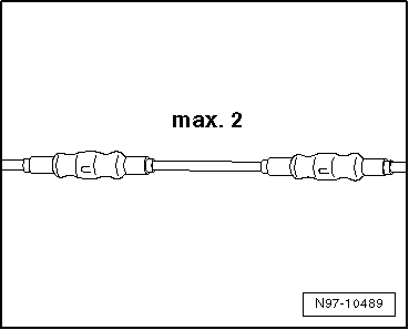
- A maximum of two repairs may be performed when repairing wires of airbag- and seat belt tensioner system. Repairs increase the electrical resistance in the wire and may trigger malfunctions in the system On Board Diagnostic (OBD).
- When repairing wiring harness of airbag- and seat belt tensioner system, the crimp connectors must always be heat-shrunk to prevent corrosion.
- Do not wrap the repair point again into the vehicle-specific wiring harness and mark the repair point quite visibly with yellow insulating tape.
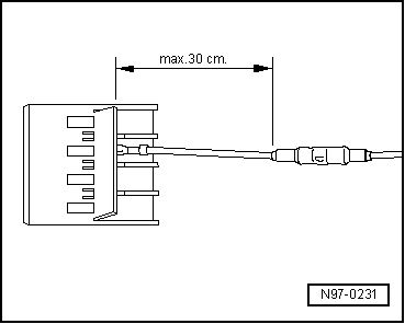
- Repairs in the area of the airbag or seat belt tensioner should be performed a maximum of 30 cm from the next connector housing. Together with the identification via yellow insulating tape, this procedure makes it possible to obtain a quick overview of previously performed repairs.
- Wires to the deploying units (airbags) have a wire-twisting with a length of lay of 20 mm +- 5 mm in series production. This length of lay is guaranteed via the norm part numbers for wire pairs in series production and must be observed strictly for the repair lengths of twisted wires.
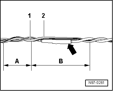
- During repair work, wires to deploying units (airbags) must have the same length. When twisting together wires -1 and 2-, length of lay of A = 20 mm +- 5 must be strictly observed.
- While doing this, no section of the wire, for example, in area of crimp connectors -arrow-, may be greater than B = 100 mm without twisting of the wires.
- Repairs are to be documented in the Audi Service Plan under "Space for workshop entries" with a short commentary of scope of repairs, workshop stamp and signature.
- Any warranty claims to Audi AG are void for repairs on airbag wiring set which were not performed using original replacement parts and Wiring Harness Repair Set -VAS1978-.
Repairing CAN bus Wires
- Unshielded, twisted two-wire lines -1 and 2- with a cross section of 0.35 mm 2 or 0.5 mm2 can be used as CAN-Bus wiring.
- Repairs on CAN-Bus wires can be performed with repair wire with matching cross section and also with twisted wires "green/yellow" or "white/yellow" from the Parts Catalog.
- When repairing CAN bus wires, both wires must be same length. When twisting together wires -1 and 2-, the lay length of A = 20 mm must be observed.
- While doing this, no section of the wire, for example, in area of crimp connectors -arrow-, may be greater than B = 50 mm without twisting of the wires.
- Wrap repair points with yellow adhesive tape to mark a performed repair.
READ NEXT:
 Repair Kit for FlexRay Wires with Coating
Note
The repair of FlexRay wires with coating can only take place
using FlexRay wires with coating from the Parts Catalog.
Observe general notes for repairs on the vehicle electrical
syst
Repairing a Wire 0.35 mm 2 or Greater with
Individual Crimp Connector
Procedure
- Free up the wire to be repaired approximately 20 cm on both
sides of the repair point.
Caution
Risk of damaging the electrical wires.
Expose wrapped wiring harnesses careful
Repair a wiring 0.35 mm 2 or greater with
intermediate wire section
Note
For the repair use repair wires with a cross section of 0.35
mm2 through 6.0-mm2.
Procedure
- Free up the wire to be repaired at two places approximately
20 cm on both sides of the
SEE MORE:
Audi connect vehicle
control services
Services
Applies to: vehicles with Audi connect vehicle control
Using Audi connect vehicle control services, you
can perform tasks such as viewing data about
your vehicle or control vehicle functions remotely.
You can view and use services available for your
vehicle at my.audi.com or through the my
Fender, Removing and Installing
Special tools and workshop equipment
required
Pop Rivet Nut Pliers -VAS5072A-
Drill
Pop rivets. Refer to the Parts Catalog.
Follow the safety precautions. Refer to
→ Body Interior; Rep. Gr.00; Safety Precautions; Safety
Precautions when Working on Pyrotechnic Components.
Remo
© 2019-2026 Copyright www.audia4b9.com
