Audi A4: Repair Kit for FlexRay Wires with Coating
 Note
Note
- The repair of FlexRay wires with coating can only take place using FlexRay wires with coating from the Parts Catalog.
- Observe general notes for repairs on the vehicle electrical system. Refer to → Chapter "Vehicle Electrical System, General Repair Information".
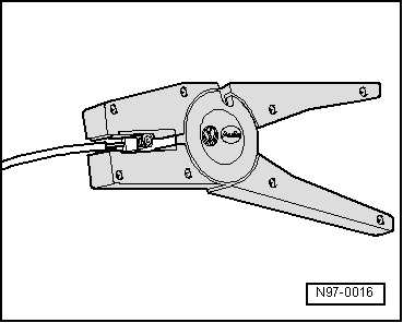
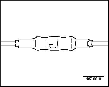
A two-layer wire -1 and 2- with a 0.35 mm 2 profile is used as a FlexRay wire.
- During repair work, both wires must have the same length.
- When twisting the wires -1 and 2- together, the -A- = 30 mm routing length must be maintained.
- While doing so, no section of wire may be greater than -B- = 50 mm without twisting the wires, for example in the area of crimp connectors -arrow-.
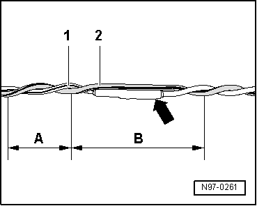
- Maximum exposed wire length: -C- = 100 mm.
- Protect the area being repairs from the environment. Use a crimp connector with heat-shrinkable tube over the untwisted location being repairs and waterproof insulation over the exposed wire.
- Mark the location of the repair with something suitable, for example, with yellow tape.
- Repairing both wires is identical to repair just one wire.
- Position both repaired location -arrows--A- = 30 mm opposite each other.
- Crimp the cables with connectors.
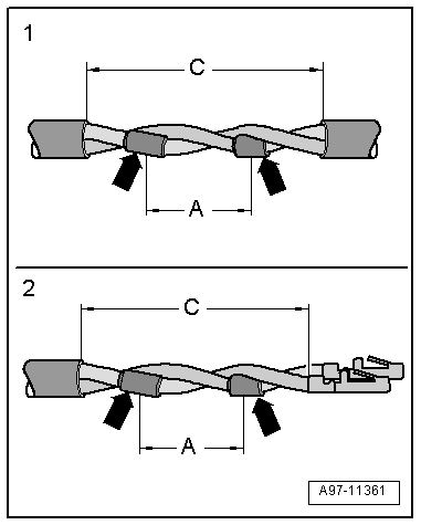
1 - Repair location in the area without insulation
2 - Repair location with connectors
C - Maximum exposed length = 100 mm
Repair Kit for FlexRay Wires without Coating
Note
- The repair of FlexRay wires without coating can only take place using FlexRay wires without coating from the Parts Catalog.
- Observe general notes for repairs on the vehicle electrical system. Refer to → Chapter "Vehicle Electrical System, General Repair Information".
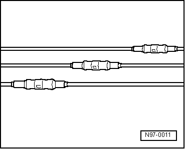
Unshielded, twisted two-wire lines -1 and 2- with a cross section of 0.35 mm 2 can be used as FlexRay wires.
- During repair work, both FlexRay wires must have the same length.
- When twisting the wires -1 and 2- together, the -A- = 20 mm routing length must be maintained.
- While doing so, no section of wire may be greater than -B- = 40 mm without twisting the wires, for example in the area of crimp connectors -arrow-.
- Mark the location of the repair with something suitable, for example, with yellow tape.
- Repairing both FlexRay wires is identical to repairing just one wire.
- Position both repaired locations -A- = 20 mm opposite each other.
- Crimp the cables with connectors.
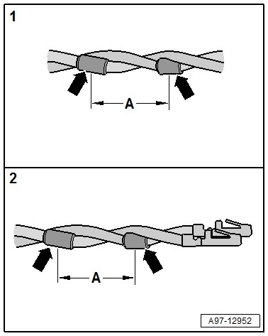
1 - Repair location in wiring harness
2 - Repair location with connectors
0.22 mm 2 Wire, Repairing with Individual Crimp Connector
Procedure
- Free up the wire to be repaired approximately 20 cm on both sides of the repair point.
 Caution
Risk of damaging the electrical wires.
Expose wrapped wiring harnesses carefully.
- If necessary, removing the wiring harness wrapping using a knife.
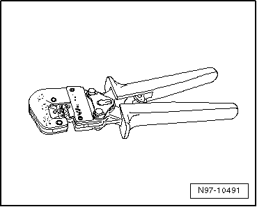
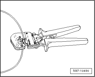
- Cut out the damaged section of wire using the Wiring Harness Repair Set - Wire Strippers -VAS1978/3-.
Note
If, by cutting out the damaged wire section, both ends of the vehicle-specific single wire are too short for a repair using a single crimp connector, insert a repair wire section of matching length with two crimp connections. Refer to → Chapter "Repairing a 0.22 mm 2 Wire with Intermediate Wire Section".
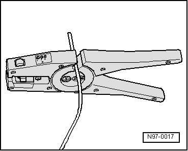
- Adjust the sliding stop in the Wiring Harness Repair Set - Wire Strippers -VAS1978/3- pliers jaws to 12 to 14 mm for the wire to be stripped.
- Insert wire end from front up to stop into jaws of pliers and squeeze the pliers completely.
- Open pliers again and remove the stripped wire end.
- Twist bare strands one-half turn.
- For the repair of a 0.22 mm 2 wire, use a small transparent crimp connector from the Wiring Harness Repair Set -VAS1978B-.
- To press the crimp connector, use the Wiring Harness Repair - Crimping Plier - Base Tool -VAS1978/1-2- with Wiring Harness Repair - Crimping Head - .35-2.5mm -VAS1978/1-1-.
- Slide the small transparent crimp connector onto both stripped, non-insulated wire ends on the vehicle-specific single wire and crimp them using crimp pliers.
Note
Do not crimp wire insulation.
After crimping, crimp connections must be heat-shrunk using hot air gun to prevent moisture penetration.
- Insert the Wiring Harness Repair - Blower - Shrink Element -VAS1978/15A- on the Wiring Harness Repair Set - Hot Air Blower -VAS1978/14A-.
Caution
Risk of damaging surrounding components.
- When heat-shrinking crimp connections, be careful not to damage any other wiring, plastic parts or insulating material with the hot nozzle of the hot air blower.
- Always observe operating instructions of heat gun.
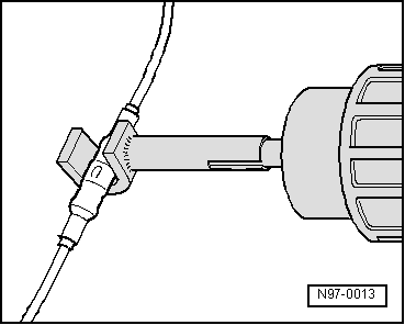
- Heat crimp connection using the hot air blower lengthwise from center outward until it is sealed completely and adhesive comes out the ends.
- This is how the completed repair location with individual crimp connector should appear.
Note
- Make sure that crimp connections do not lie directly next to each other when several wires need to be repaired. Arrange the crimp connectors at a slight offset so that the circumference of the wiring harness does not become too large.
- If the repair point was previous taped, this point must be taped again with yellow insulating tape after repairs.
- Secure the repaired wiring harness if necessary with a cable tie to prevent flapping noises while driving.
READ NEXT:
 Repairing a Wire 0.35 mm 2 or Greater with
Individual Crimp Connector
Repairing a Wire 0.35 mm 2 or Greater with
Individual Crimp Connector
Procedure
- Free up the wire to be repaired approximately 20 cm on both
sides of the repair point.
Caution
Risk of damaging the electrical wires.
Expose wrapped wiring harnesses careful
Repair a wiring 0.35 mm 2 or greater with
intermediate wire section
Note
For the repair use repair wires with a cross section of 0.35
mm2 through 6.0-mm2.
Procedure
- Free up the wire to be repaired at two places approximately
20 cm on both sides of the
Fiber-Optic Cables, Repairing
Caution
Do not bend the fiber-optic cable too much. The
bending radius must be no less than 25 mm.
Fiber optic cables must not be routed over sharp
edges.
The fiber-optic cable must not be
SEE MORE:
Mounting Bracket, Removing and Installing
NOTICE
Risk of damaging the operating cable by deforming it.
- Never sharply bend or kink the operating cable.
Removing
- Move the door window into the "closed" position.
- Remove the door handle. Refer to
→ Chapter "Door Handle, Removing and Installing".
- Driver
Overview - Steering Gear
Overview - Steering Gear
1 - Bolt
Replace after removing
Tightening specification -Item 2-
2 - Subframe Crossbrace
Overview. Refer to
→ Chapter "Overview - Subframe".
3 - Steering Gear with Tie Rods
With integrated Power Steering Control Module -J500-
