Audi A4: Repair a wiring 0.35 mm 2 or greater with intermediate wire section
 Note
Note
For the repair use repair wires with a cross section of 0.35 mm2 through 6.0-mm2.
Procedure
- Free up the wire to be repaired at two places approximately 20 cm on both sides of the repair point.
 Caution
Risk of damaging the electrical wires.
Expose wrapped wiring harnesses carefully.
- If necessary, removing the wiring harness wrapping using a knife.
- Route the yellow repair wire next to the damaged wiring harness and cut the repair wire to the required length using the Wiring Harness Repair Set - Wire Strippers -VAS1978/3-.
- Cut damaged wire section from the vehicle-specific single wire.
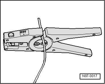
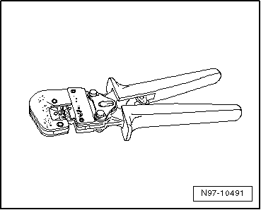
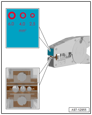
- Adjust the sliding stop in the Wiring Harness Repair Set - Wire Strippers -VAS1978/3- pliers jaws to 6 to 7 mm for the wire to be stripped.
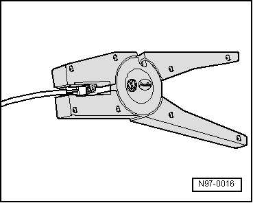
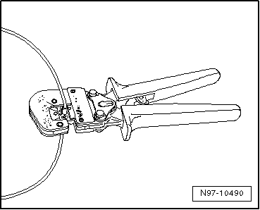
- Insert the vehicle-specific single wire end from the front into the pliers jaws as far as the stop and squeeze the pliers together completely.
- Open pliers again and remove the stripped wire end.
- Repeat the procedure on the other end of the vehicle-specific individual wire.
- For the repair, use two suitable crimp connectors from the Wiring Harness Repair Set -VAS1978B-.
Note
- Always be sure to use the corresponding crimp connector and the correct crimping slot for the crimping connection used. Refer to → Chapter "Crimping Pliers with Insert".
- Do not crimp wire insulation.
- Use the Wiring Harness Repair - Crimping Plier - Base Tool -VAS1978/1-2- to press the crimp connector.
The following exchangeable heads are available for the Wiring Harness Repair - Crimping Plier - Base Tool -VAS1978/1-2-:
- Wiring Harness Repair - Crimping Head - .35-2.5mm -VAS1978/1-1-
- Wiring Harness Repair Set - Crimping Head - 4-6mm -VAS1978/2 A-
- Slide the crimp connector onto the vehicle-specific single wire at one side and onto repair wire at the other side.
- Crimp the crimp connection at both wire ends using crimp pliers.
- Repeat this procedure on the other wire ends.
Note
Do not crimp wire insulation.
After crimping, crimp connections must be heat-shrunk using hot air gun to prevent moisture penetration.
- Insert the Wiring Harness Repair - Blower - Shrink Element -VAS1978/15A- on the Wiring Harness Repair Set - Hot Air Blower -VAS1978/14A-.
Caution
Risk of damaging surrounding components.
- When heat-shrinking crimp connections, be careful not to damage any other wiring, plastic parts or insulating material with the hot nozzle of the hot air blower.
- Always observe operating instructions of heat gun.
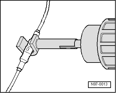
- Heat crimp connection using the hot air blower lengthwise from center outward until it is sealed completely and adhesive comes out the ends.
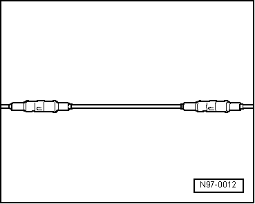
- This is how the completed repair location with the inserted wire and two crimp connectors should look.
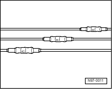
Note
- Make sure that crimp connections do not lie directly next to each other when several wires need to be repaired. Arrange the crimp connectors at a slight offset so that the circumference of the wiring harness does not become too large.
- If the repair point was previous taped, this point must be taped again with yellow insulating tape after repairs.
- Secure the repaired wiring harness if necessary with a cable tie to prevent flapping noises while driving.
10 mm2- or 16 mm2 Wires with Separate Butt Connectors, Repairing
Special tools and workshop equipment required
- Wiring Harness Repair Set - Hot Air Blower -VAS1978/14A- from the Wiring Harness Repair Set -VAS1978B-
- Wiring Harness Repair - Blower - Shrink Element -VAS1978/15A- from the Wiring Harness Repair Set -VAS1978B-
- Wiring Harness Repair Set VAS 631 003 -VAS631003-
Note
- For the repair there are repair wires with a 10mm2 or 16mm2 cross section.
- There are also separate repair wires with a crimped on/connected contact available for the repair.
Procedure
- For the wire cross-section install the suitable crimp insert and crimp stamp as follows on the crimping pliers:
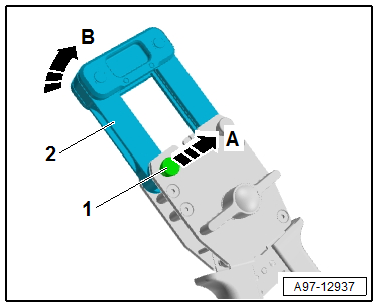
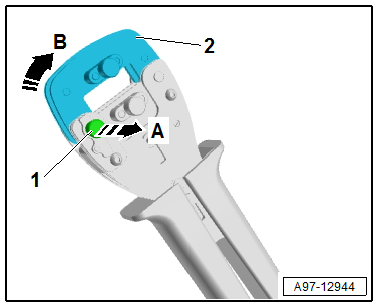
- Open the crimping pliers from the Wiring Harness Repair Set -VAS631003-.
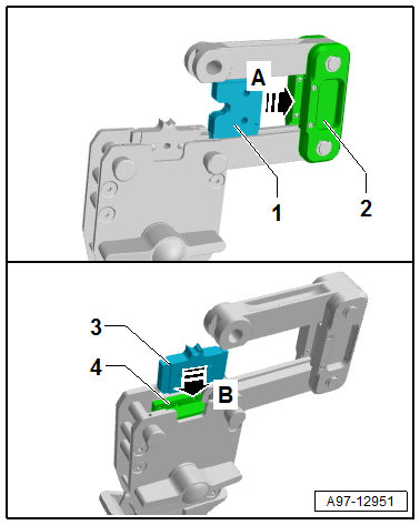
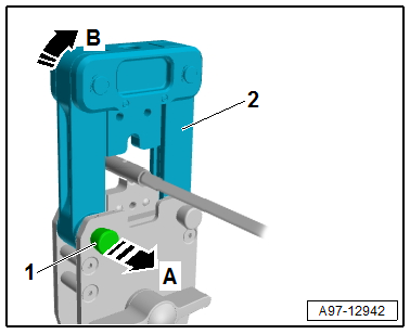
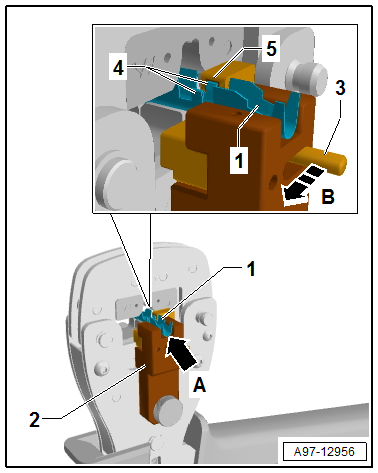
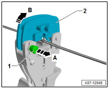
- Remove the locking pin -1- all the way in the direction of -arrow A-.
- Open the adapter -2- in the direction of -arrow B-.
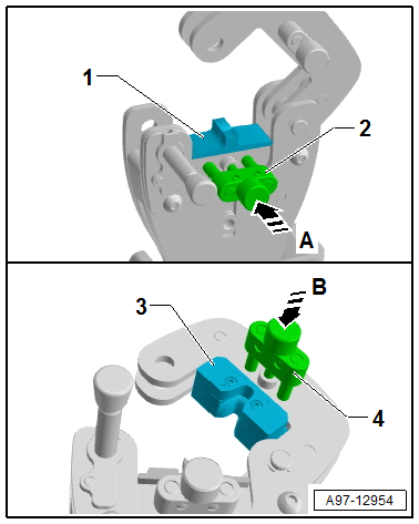
- Push in the crimp stamp -1- until it clicks into place in the mount -2- on the adapter -arrow A-.
- Push in the crimp insert -3- until it engages audibly in the mount -4- of the crimping pliers -arrow B-.
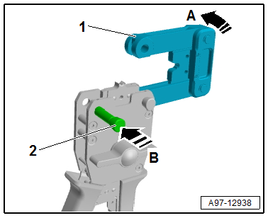
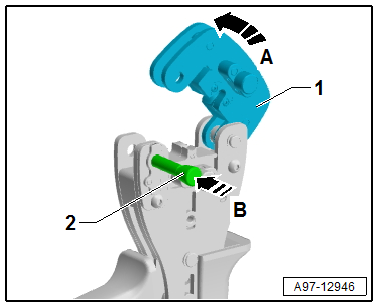
- Close the adapter -1- in the direction of -arrow A-.
- Push the locking pin -2- in the direction of -arrow- all the way.
- Free up the wire to be repaired approximately 20 cm on both sides of the repair point.
Caution
Risk of damaging the electrical wires.
Expose wrapped wiring harnesses carefully.
- If necessary, removing the wiring harness wrapping using a knife.
- Cut the damaged section of the wire with wire cutters from the Wiring Harness Repair Set -VAS631003-.
Note
- When both ends of the vehicle-specific single wire are too short after cutting out the damaged wire section for a repair with a separate butt connector, insert a corresponding long piece of yellow repair wire with two butt connectors.
- When repairing the single wire with crimped on/connected contact place the yellow repair wire near the damaged vehicle-specific single wire and cut to the required length.
- Adjust the sliding stop in the wire stripper pliers jaws from the Wiring Harness Repair Set -VAS631003- to the length for the wire to be stripped.
- 10 mm2 wires: 14 mm
- 16 mm2 wires: 16.5 mm
- Insert wire end from front up to stop into jaws of pliers and squeeze the pliers completely.
- Open pliers again and remove the stripped wire end.
- The insolation must be cut cleanly and remove from the wires.
- No insolation can remain on bare wires.
- The single wires must not be damaged.
- For the repair remove the corresponding butt connection and a heat-shrinkable tube from the Wiring Harness Repair Set -VAS631003-.
- Push the heat-shrinkable tube on one of the wires.
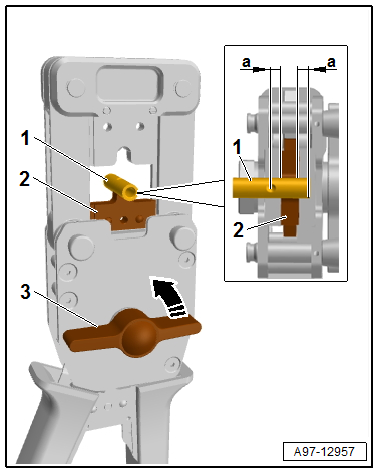
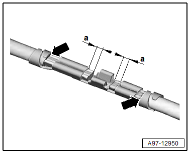
- Position the butt connection -1- with the first crimping position centered on the crimp insert -2-.
- The dimension -a- must be the same on both sides
- Turn the quick feed lever -3- counter-clockwise -arrow- until the butt connection -1- is secured.
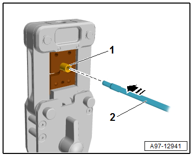
- Insert the wire -2- with the bare wire end all the way in the butt connection -1--arrow-.
- All single wires must be pushed into the butt connection.
- Completely close and open the crimping pliers several times, until the crimp insert goes downward by itself in its original position.
Note
The wire insulation must not be crimped at the same time.
- Repeat the wire crimping on the other side as described.
- Remove the securing pin in the direction of -arrow A- until it stops.
- Open the adapter in the direction of -arrow B-.
- Remove the crimped butt connectors.
Correct crimping results
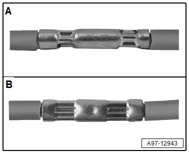
A - 10 mm2, Star crimp
B - 16 mm2, B-Crimp
After crimping the heat-shrinkable tube must positioned over the butt connection and heat-shrunk with a hot air gun, to prevent moisture from entering.
- Insert the Wiring Harness Repair - Blower - Shrink Element -VAS1978/15A- on the Wiring Harness Repair Set - Hot Air Blower -VAS1978/14A-.
Caution
Risk of damaging surrounding components.
- When heat-shrinking the heat-shrinkable tube, be careful not to damage any other wiring, plastic parts or insulating material with the hot nozzle of the hot air blower.
- Always observe operating instructions of heat gun.
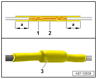
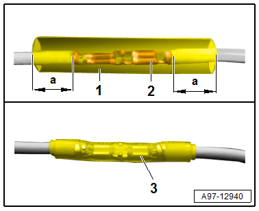
- Position the heat-shrinkable tube -1- by feeling the contours centered over the butt connection -2-.
- The dimension -a- must be approximately the same on both sides
- Heat the heat-shrinkable tube using the hot air blower lengthwise from center outward until it is sealed completely and adhesive comes out the ends.
- The completed repair location -3- must look like so.
Note
- Make sure that the butt connections do not lie directly next to each other when several wires need to be repaired. Arrange the butt connection at a slight offset so that the circumference of the wiring harness does not become too large.
- If the repair point was previous taped, this point must be taped again with yellow insulating tape after repairs.
- Secure the repaired wiring harness if necessary with a cable tie to prevent flapping noises while driving.
Early Release
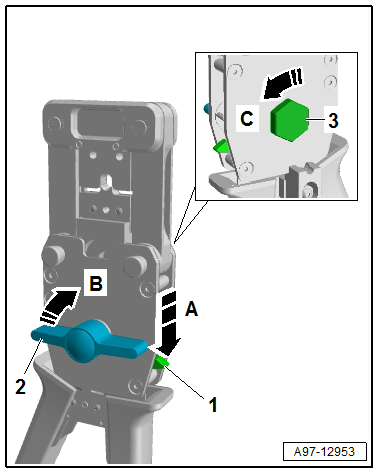
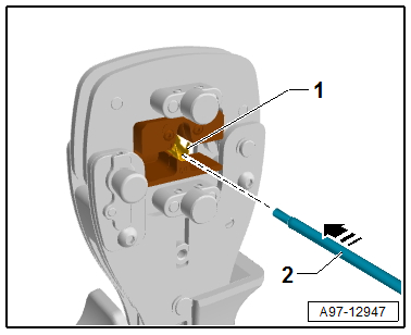
- Push the lever -1- downward in direction of -arrow A-.
- Turn the quick feel lever -2- clockwise in direction of -arrow B- until the crimp insert is in its original position.
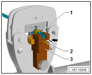
If releasing by hand is not possible then:
- Push the lever -1- downward in direction of -arrow A-.
- Place the socket from the Wiring Harness Repair Set -VAS 631 003- on the bolt -3- on the rear side.
- Turn the socket counter-clockwise in direction of -arrow C- until the crimp insert is in its original position,
Caution
Do not use the butt connectors after they are early released.
2.,5 mm2, 4 mm2 or 6 mm2 Aluminum Wires with Separate Butt Connectors, Repairing
Special tools and workshop equipment required
- Wiring Harness Repair Set - Hot Air Blower -VAS1978/14A- from the Wiring Harness Repair Set -VAS1978B-
- Wiring Harness Repair - Blower - Shrink Element -VAS1978/15A- from the Wiring Harness Repair Set -VAS1978B-
- Wiring Harness Repair Set -VAS631001-
Note
- For the repair there are copper repair wires with a 2.5mm2 or 4 mm2 or 6 mm2 cross section.
- There are also separate copper repair wires with a crimped on contacts available for the repair.
Procedure
- Install the corresponding crimp insert, crimp stamp and contact positioner for the wire cross-section with the contact cross bar as follows on the crimping tool.
- Open the crimping tool from the Wiring Harness Repair Set -VAS 631 001-.
- Remove the locking pin -1- all the way in the direction of -arrow A-.
- Open the mount -2- in the direction of -arrow B-.
- Insert the crimp insert -1- in the crimping tool so that the crimp insert -1- is flush with the front of the clamps.
- Tighten the crimp insert with the pins -2- in direction of -arrow A- and the knurled screw hand tight.
- Insert the crimp stamp -3- that fits the crimp insert in the mount.
- Secure the crimp stamp with the pin -4- in direction of -arrow B- and the knurled screw hand-tight.
- Close the adapter -1- in the direction of -arrow A-.
- Push the locking pin -2- in the direction of -arrow- all the way.
- Insert the contact cross bar -1- in the contact positioner -2-.
- Position the contact positioner with the contact cross bar on the crimping tool -5- at the same time push the holes in the contact positioner -2- over the knurled screw -4-.
- Install the knurled bolt -3- and tighten hand-tight.
- Free up the wire to be repaired approximately 20 cm on both sides of the repair point.
Caution
Risk of damaging the electrical wires.
Expose wrapped wiring harnesses carefully.
- If necessary, removing the wiring harness wrapping using a knife.
- Cut the damaged section of the wire with wire stripper from the Wiring Harness Repair Set -VAS 631 001-.
Note
When both ends of the vehicle-specific single wire are too short after cutting out the damaged wire section for a repair with a separate butt connector, insert a corresponding long piece of yellow copper repair wire with two butt connectors.
- Insert the wire end from the front all the way in to the wire cross-section corresponding mount in the jaws of the pliers.
- Push the pliers completely together.
- Open pliers again and remove the stripped wire end.
- The insolation must be cut cleanly and remove from the wires.
- No insolation can remain on bare wires.
- The single wires must not be damaged.
- For the repair remove the corresponding butt connection with a heat-shrinkable tube from the Wiring Harness Repair Set -VAS 631 001-.
- Push the heat-shrinkable tube on one of the wires.
- Place the butt connection -1- in the contact positioner -2-.
- The butt connection -1- must be flush with the contact positioner -2--arrow A-.
- Push the contact cross bar -3- all the way in the direction of the -arrow B- and secure it with the butt clamp -1-.
- The tab -4- on the butt connection -1- must engage in the groove -5- on the contact cross bar -3-.
- Insert the wire -2- with the bare wire end all the way in the butt connection -1--arrow-.
- All single wires must be pushed into the butt connection.
- The insolation end can at a maximum be flush with the front edge of the insolation crimps.
- Close the crimping tool completely until it reopens by itself.
- Push the contact cross bar -2- all the way in the direction of -arrow-.
- Remove the butt connection -1- from the contact positioner -3-.
- Turn the crimping tool for the second crimping.
- Repeat the wire crimping on the other side as described.
- Remove the securing pin -1- in the direction of -arrow A- until it stops.
- Open the mount -2- in the direction of -arrow B-.
- Remove the crimped butt connectors.
Correct crimping results
- The wire ends must project 0.1 mm to 1.0 mm on the front edge of the wire crimps, dimension -a-
- The insolation end must not be crimped in the wire crimps.
- The insolation end can at a maximum be flush with the front edge of the insolation crimps -arrows-.
After crimping the heat-shrinkable tube must positioned over the butt connection and heat-shrunk with a hot air gun, to prevent moisture from entering.
- Insert the Wiring Harness Repair - Blower - Shrink Element -VAS 1978/15A- on the Wiring Harness Repair Set - Hot Air Blower -VAS 1978/14A-.
Caution
Risk of damaging surrounding components.
- When heat-shrinking the heat-shrinkable tube, be careful not to damage any other wiring, plastic parts or insulating material with the hot nozzle of the hot air blower.
- Always observe operating instructions of heat gun.
- Position the heat-shrinkable tube -1- centered over the butt connection -2-.
- The dimension -a- must be approximately the same on both sides
- Heat the heat-shrinkable tube using the hot air blower lengthwise from center outward until it is sealed completely and adhesive comes out the ends.
- The completed repair location -3- must look like so.
Note
- Make sure that the butt connections do not lie directly next to each other when several wires need to be repaired. Arrange the butt connection at a slight offset so that the circumference of the wiring harness does not become too large.
- If the repair point was previous taped, this point must be taped again with yellow insulating tape after repairs.
- Secure the repaired wiring harness if necessary with a cable tie to prevent flapping noises while driving.
READ NEXT:
 Fiber-Optic Cables, Repairing
Caution
Do not bend the fiber-optic cable too much. The
bending radius must be no less than 25 mm.
Fiber optic cables must not be routed over sharp
edges.
The fiber-optic cable must not be
Antenna Wires, Repairing
Aerial Cable Repair Set VAS6720
Special tools and workshop equipment required
Aerial Cable Repair Set -VAS6720-
The Aerial Cable Repair Set -VAS6720- makes it possible to
perform a quality repair
Connector Housings and Connectors, Repairing
Connector Housings and Connectors, Repair Information
Note
Observe general notes for repairs on the vehicle electrical
system. Refer to
→ Chapter "Vehicle Electrical System, General
SEE MORE:
Instrument Panel Central Tube
Overview - Instrument Panel Central Tube
1 - Bolt
20 Nm
Quantity: 2
The mounting threads and contact surface must be free of paint, coating,
and corrosion. The threaded connection serves as the ground connection
2 - Threaded Pin
20 Nm
Quantity: 2
3 - Lifter
Refrigerant Circuit
Refrigerant Circuit with Expansion Valve and Evaporator
The following illustration shows only the principle of a
refrigerant circuit, the design of the refrigerant circuit in
the respective vehicle can be found in the vehicle-specific
repair manual. Refer to
→ Heating, Ventilation and Air
