Audi A4: Connector Housings and Connectors, Repairing
Connector Housings and Connectors, Repair Information
 Note
Note
- Observe general notes for repairs on the vehicle electrical system. Refer to → Chapter "Vehicle Electrical System, General Repair Information".
- Allocation of crimp contacts with correct fit to connector housing is performed according to the part number stamped in on the connector housing. Refer to the Parts Catalog; Special Catalog "Electrical Connecting Components"; Electrical Equipment; subgroup 71 chart 970-00.
- Damaged connector housings must always be replaced.
Contacts in Connector Housing, Repairing
Procedure
- First, open or release if necessary the secondary lock of the connector housing. Refer to → Chapter "Connector Housings, Releasing and Disassembling".
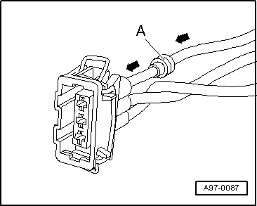
- Release contact (primary lock) using the appropriate release tool. Refer to → Chapter "Connector Housings, Releasing and Disassembling".
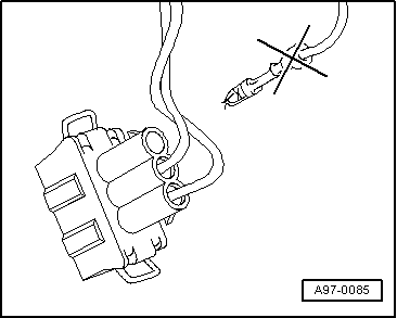
- Pull the contact back out of the connector housing -arrow- at the single wire (with the single wire seal if necessary).
- Cut off the old contact (with the single wire seal) from the vehicle-specific wiring harness.
- Take the yellow repair wire with the correct contact out of the Wiring Harness Repair Set -VAS1978B-.
- Free up the wire to be repaired approximately 20 cm on both sides of the repair point.
 Caution
Risk of damaging the electrical wires.
Expose wrapped wiring harnesses carefully.
- If necessary, removing the wiring harness wrapping using a knife.
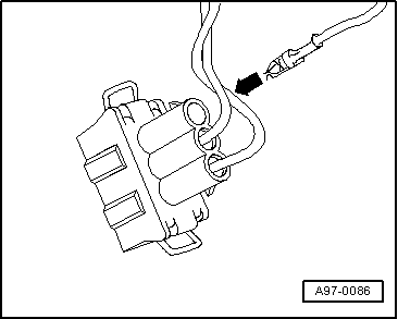
- Slide the new repair wire contact into the corresponding connector housing compartment until it engages.
- If necessary, install the single wire seal on the repair wire. Refer to → Chapter "Single Wire Seals, Installing".
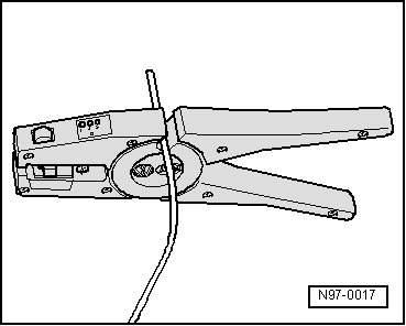
- Shorten the repair wire and the vehicle-specific wiring harness single wire as needed using the Wiring Harness Repair Set - Wire Strippers -VAS1978/3-.
- Remove the insulation from the ends of the repair wire and vehicle-specific single wire and crimp the ends with the crimping wires and a crimp connector. Refer to → Chapter "0.22 mm 2 Wire, Repairing with Individual Crimp Connector" or → Chapter "Repairing a Wire 0.35 mm 2 or Greater with Individual Crimp Connector".
Single Wire Seals, Installing
Procedure
Note
- Single wire seals prevent the penetration of water and dirt into the connector housing. They are installed, for example, in the engine compartment and must be reinstalled after a repair.
- Single wire seal is crimped on at the factory together with contact on the wire, this is not the case for repair wires. The single wire seal must be slid onto the wire before crimping the repair wire.
- Single wire seals must always fit with the repair wire cross-section. Outer circumference of single wire seal is aligned according to chamber circumference of the connector housing. Perform assembly using only the assembly tool with correct fit.
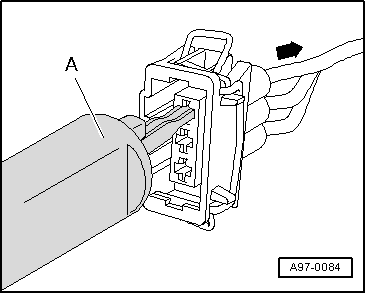
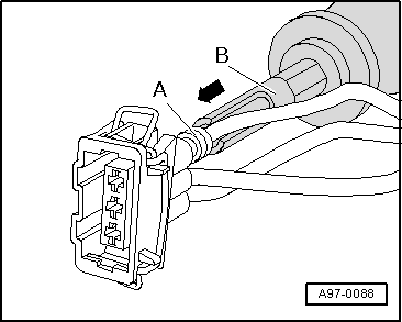
- Put single wire seal -A- onto free end of repair wire.
- When doing this, the single wire seal small diameter must point toward the connector housing.
- Slide the single wire seal -A- onto the repair wire up to the connector housing and then into the housing as far as the stop using the appropriate assembly tool -B-.
- Shorten the repair wire and the vehicle-specific wiring harness single wire as needed using the Wiring Harness Repair Set - Wire Strippers -VAS1978/3-.
- Crimp the stripped ends of repair wire and single wire of vehicle-specific wiring harness using crimping pliers and a crimping pliers. Refer to → Chapter "0.22 mm 2 Wire, Repairing with Individual Crimp Connector" or → Chapter "Repairing a Wire 0.35 mm 2 or Greater with Individual Crimp Connector".
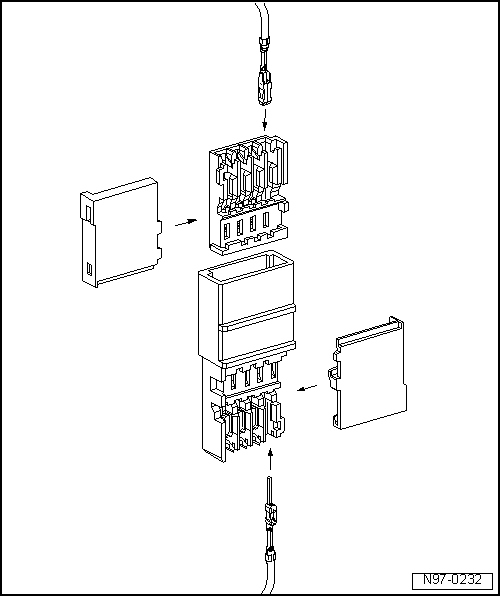
Connector Housing with Insulation Displacement Connections, Repairing
Note
- For technical reasons, the connector housing for the wire terminals can be supplied only with the contacts pushed in.
- These contacts can be removed at every other connector housing in the event they are not required.
- Repair wires which have already been equipped with corresponding contacts crimped on are available. Refer to the Parts Catalog.
READ NEXT:
 Connector Housings, Releasing and Disassembling
Information on Releasing and Disassembling Connector Housings
Note
Observe general notes for repairs on the vehicle electrical
system. Refer to
→ Chapter "Vehicle Electrical System,
Contact Surface Cleaning Set -VAS6410-
Contact Surface Cleaning Set -VAS6410-, Using
The Contact Surface Cleaning Set -VAS6410- makes optimal
repair quality possible in the realm of vehicle electronics.
Using the tools, service work can
ESD Work Surface -VAS6613-
The electro-static discharge ESD Work Surface -VAS6613-
protect electronic components from getting damaged by an
electro-static charge.
This makes is possible to perform repairs on sensitive
ele
SEE MORE:
Operating in the cockpit
Fig. 92 3-zone deluxe automatic climate control system: controls
Press the knobs, buttons or rocker switches to
turn the functions on or off. When the function is
switched on, the LED in the respective button or
knob turns on. Some rocker switches can be assigned
with multiple functions. The variou
General Information
Caution
There is a risk of damaging the threads in the
vehicle body.
The bolts and nuts at all suspension parts must not
be loosened or tightened with an impact wrench.
Always install the bolts and nuts by hand for the
first few turns.
When installing waxed components, contact surf
