Audi A4: Connector Housings, Releasing and Disassembling
Information on Releasing and Disassembling Connector Housings
 Note
Note
- Observe general notes for repairs on the vehicle electrical system. Refer to → Chapter "Vehicle Electrical System, General Repair Information".
- Always use the release tools intended for the releasing process. Under no circumstances may terminals be pulled forcefully out of connector housings.
- Damaged connector housings must always be replaced. New connector housings may be ordered via OTC Kassel.
- Small screwdrivers may be used as an aid to release the secondary locks.
- The chamber/connector assignment is partially stamped on the secondary lock or the rear side of the connector housing.
- Detailed information on component locations of harness connectors. Refer to → Wiring diagrams, Troubleshooting & Component locations.
The allocation of the correct release tools to the respective locking mechanisms can be found in the table in the Release Tool Set -VAS1978/35- Operating Instructions.
Secondary Lock
The secondary lock is a housing securing mechanism (second locking mechanism) that secures all wires in one connector housing. If a secondary lock is installed at a connector housing, it must always be opened or removed using specified tool before releasing and pulling out individual crimp contacts.
Secondary lock is distinguished by a different color from the rest of the connector housing. It simplifies recognizing the secondary lock and clarifies its function.
The shapes of the connector housings depicted here are only a selection which, as an example, should make clear the various functions of the secondary lock.
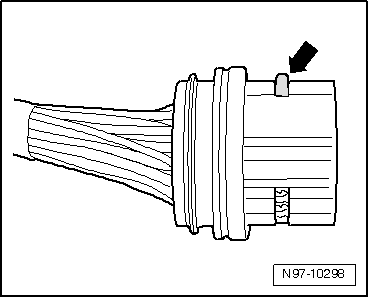
Example 1
Housing securing mechanism is released by removing a "comb"-arrow-.
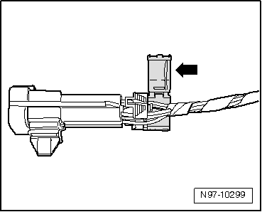
Example 2
Housing securing mechanism is released by opening a "flap"-arrow-.
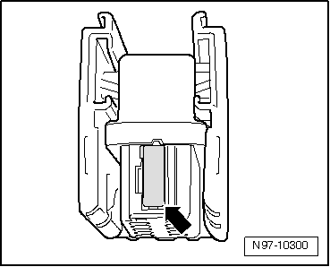
Example 3
Housing securing mechanism can be released by disengaging a "slider"-arrow-.
Primary Lock
The primary lock is the locking mechanism of an individual crimp contact in the connector housing.
If necessary, housing securing mechanisms (secondary locks) must be released or removed using specified tool before releasing the contacts. Refer to → Chapter "Secondary Lock".
The shapes of the primary locks depicted in the following are only a selection which, as an example, should make clear the various functions of the primary lock.
- Round connector systems. Refer to → Chapter "Round Connector Systems".
- Flat connector systems. Refer to → Chapter "Flat Connector Systems".
- Special connector systems. Refer to → Chapter "Special Connector Systems".
The allocation of the correct release tool for the respective locks can be found in the table in the Release Tool Set -VAS1978/35- Operating Instructions.
Round Connector Systems
Note
If necessary, housing securing mechanisms (secondary locks) must be released or removed using specified tool before releasing the contacts. Refer to → Chapter "Secondary Lock".
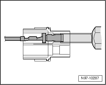
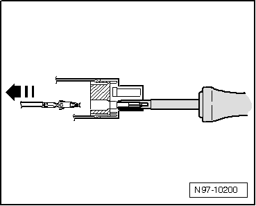
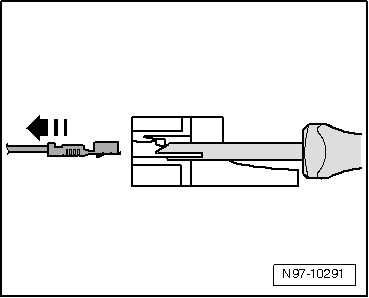
- Guide the release tool which fits the connector housing into release channel on connector housing.
- Grasp contact at wire and push it gently into connector housing in direction of -arrow-.
Note
By pushing the contact in the direction of the connector housing, contact retaining tabs are lifted off the housing shoulder and released using the release tool.
- At the same time, push the release tool in the direction of the connector housing -arrow- and pull the released contact out of the connector housing.
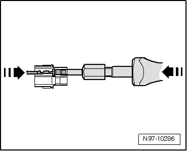
- After removing the contact, release tool can be pulled out of the connector housing again.
Flat Connector Systems
Note
If necessary, housing securing mechanisms (secondary locks) must be released or removed using specified tool before releasing the contacts. Refer to → Chapter "Secondary Lock".
Flat Connector System with One Retaining Tab
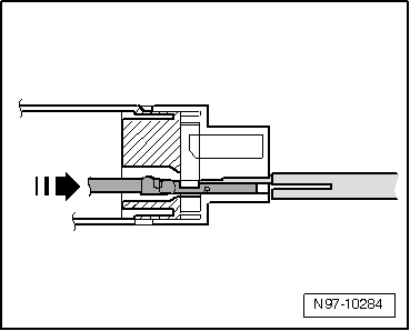
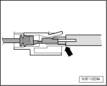
- Guide the release tool which fits the connector housing into release channel on connector housing.
- Grasp contact at wire and push it gently into connector housing in direction of -arrow-.
Note
By pushing the contact in the direction of the connector housing, the contact retaining tab is lifted off the housing shoulder and can be released using the release tool.
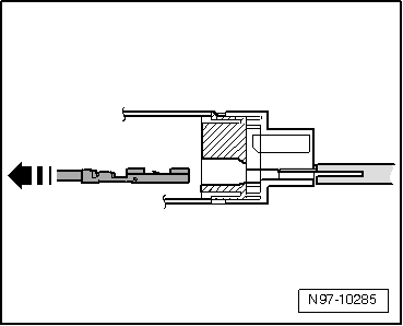
- At the same time, push the release tool in the direction of the connector housing and pull the released contact out of the connector housing in direction of -arrow-.
- After removing the contact, release tool can be pulled out of the connector housing again.
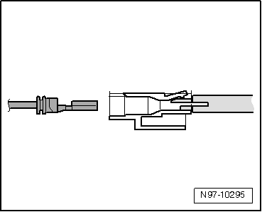
Flat Connector System with Two Retaining Tabs
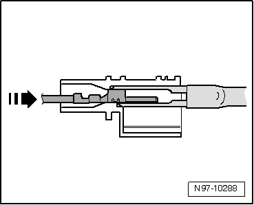
- Guide the release tool which fits the connector housing into release channel on connector housing.
- Grasp contact at wire and push it gently into connector housing until it stops -arrow-.
Note
By pushing the contact in the direction of the connector housing, contact retaining tabs are lifted off the housing shoulder and released using the release tool.
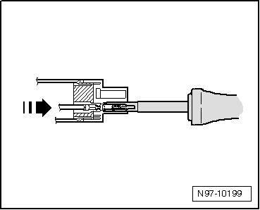
- At the same time, push the release tool in the direction of the connector housing and pull the released contact out of the connector housing -arrow-.
- After removing the contact, release tool can be pulled out of the connector housing again.
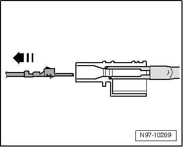
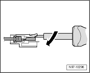
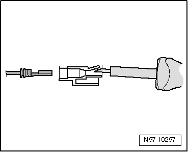
Asymmetrical
- Guide the release tool which fits the connector housing into release channel on connector housing.
- Grasp contact at wire and push it gently into connector housing -arrow-.
Note
By pushing the contact in the direction of the connector housing, contact retaining tabs are lifted off the housing shoulder and released using the release tool.
- At the same time, push the release tool in the direction of the connector housing and pull the released contact out of the connector housing -arrow-.
- After removing the contact, release tool can be pulled out of the connector housing again.
Special Connector Systems
Note
If necessary, housing securing mechanisms (secondary locks) must be released or removed using specified tool before releasing the contacts. Refer to → Chapter "Secondary Lock".
Fasten Contacts
- Guide the release tool which fits the connector housing into release channel on connector housing.
- Grasp contact at wire and push it gently into connector housing.
Note
By pushing the contact in the direction of the connector housing, contact retaining tabs are lifted off the housing shoulder and released using the release tool.
- At the same time, push the release tool in the direction of the connector housing and pull the released contact out of the connector housing -arrow-.
- After removing the contact, release tool can be pulled out of the connector housing again.
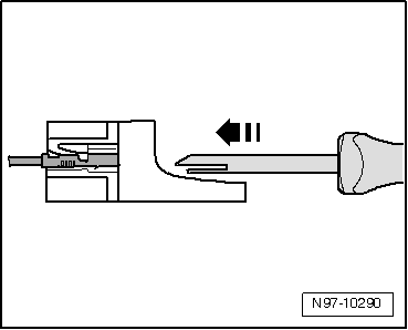
GT 150/280 Contacts
- Guide the release tool which fits the connector housing under retaining tab into connector housing.
- Push tool into connector housing until it stops -arrow-.
Contact is ejected from the connector housing.
- After ejecting the contact, release tool can be pulled out of the connector housing again.
Contacts without Retaining Tabs
- Insert release tool under retaining tab of connector housing.
- Push release tool through until it stops by gently lifting -arrow-.
Contact is ejected from the connector housing.
READ NEXT:
 Contact Surface Cleaning Set -VAS6410-
Contact Surface Cleaning Set -VAS6410-, Using
The Contact Surface Cleaning Set -VAS6410- makes optimal
repair quality possible in the realm of vehicle electronics.
Using the tools, service work can
ESD Work Surface -VAS6613-
The electro-static discharge ESD Work Surface -VAS6613-
protect electronic components from getting damaged by an
electro-static charge.
This makes is possible to perform repairs on sensitive
ele
Radio Installation Instructions
Retrofitting Radio Systems
General Information
Before installing radios and telephone systems (radio
systems), disconnect the negative terminal of the Battery -A-.
Refer to
→Electrical Equipment;
SEE MORE:
Head restraints
General information
Applies to: vehicles with adjustable head restraints
Fig. 61 Correctly-adjusted head restraint
Make sure that:
The upper edge of the head restraint is as even
as possible with the top of your head
The head restraint is as close as possible to the
back of the head
The head
Mounting Bracket, Removing and Installing
NOTICE
Risk of damaging the operating cable by deforming it.
- Never sharply bend or kink the operating cable.
Removing
- Move the door window into the "closed" position.
- Remove the door handle. Refer to
→ Chapter "Door Handle, Removing and Installing".
- Driver
