Audi A4: Fiber-Optic Cables, Repairing
 Caution
Do not bend the fiber-optic cable too much. The bending radius must be no less than 25 mm.
Fiber optic cables must not be routed over sharp edges.
The fiber-optic cable must not be dirty or touched with bare fingers.
Fiber optic cables may not be heated.
It is not permitted to twist together 2 fiber optic cables or one fiber optic cable with a copper wire.
Protect the connector and the connection box from dust. Place the cap on the trunk.
Determine Position of the Error
Special tools and workshop equipment required
- Vehicle Diagnostic Tester
Procedure
It is very difficult to find the exact location of the problem. Replace the damaged fiber-optic cable and lay a new wire parallel to the defective fiber-optic cable.
 Note
Note
- Via the "Guided Fault Finding" it can be determines which component of the fiber-optic cable is damaged.
- A fiber-optic cable that needs repair is represented by a "yellow" color.
- Perform in the "Off-board Diagnostic Information System Service" the "Ring break diagnosis" function in the Vehicle Diagnostic Tester.
- Remove the affected components.
- Disconnect the connector from the components.
- Assemble the fiber-optic cable:
- Refer to → Chapter "Fiber-Optic Cable, Preparing with the Fiber-Optic Conductor Repair Set -VAS6223A-"
- Refer to → Chapter "Fiber-Optic Cable, Preparing with the Fiber-Optic Conductor Repair Set -VAS6223A-"
Fiber-Optic Cable, Preparing with the Fiber-Optic Conductor Repair Set -VAS6223A-
Special tools and workshop equipment required
- Fiber Optic Repair Set -VAS6223B-
- Hose Cutting Pliers -VAS6228-
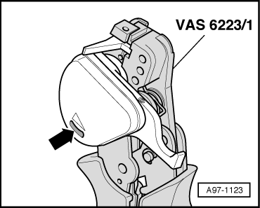
Checking Remaining Cut Indicator
- Start by checking remaining cut indicator:
- The Fiber-Optic Repair Set - Pliers -VAS6223/1- cutting device can perform approximately 1260 cuts. The blade is rotated for each further cut.
- The remaining cut indicator -arrow - displays the last 150 cuts available.
- Once no further cuts are available, the blade is blocked. It must be replaced. Refer to the Operating Instructions that come with Fiber-Optic Repair Set - Pliers -VAS6223/1-.
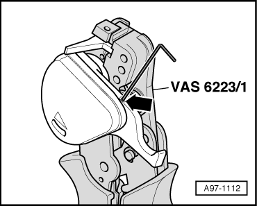
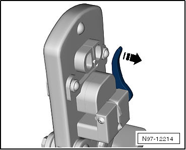
Fiber-Optic Repair Set - Pliers -VAS6223/1- Preparing
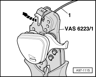
- Release the transport safety device on the cutter by loosening the bolt -arrow-.
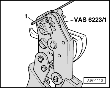
Fiber Optic Cable, Cutting to Length
- Establish length of fiber optic cable required.
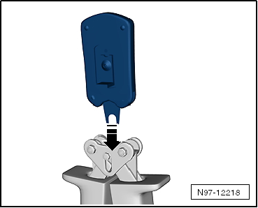
- Open Fiber-Optic Repair Set - Pliers -VAS6223/1- and insert fiber-optic cable -1- into trimming station.
- Close cutting tool to cut fiber optic cable to length.
Stripping
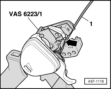
- Open the Fiber-Optic Repair Set - Pliers -VAS6223/1-.
- Stripping lever must be in lower position -arrow-.
- Place the fiber optic cable -1- in the stripping point.
- The end of the fiber-optic cable must be flush with the rear side of the cutting pliers.
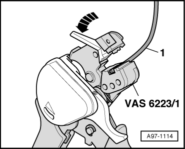
- Close Fiber-Optic Repair Set - Pliers -VAS6223/1- until stop and keep closed.
- Lift the stripping lever -arrow- upward.
- Open the cutting tool and take out the fiber-optic cable -1-.
- Detach the separated section of the insulation from the fiber-optic cable.
Precision Cutting (production of optical end face)
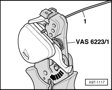
- Slide the fiber-optic cable -1- into the cutting station.
- The insulation must make contact with the cutting point stop -arrow-.
- Close the Fiber-Optic Repair Set - Pliers -VAS6223/1-.
- Press the cutting unit down -arrow-.
- Open Fiber-Optic Repair Set - Pliers -VAS6223/1- and remove fiber-optic cable -1-.
Note
The fiber-optic cable should only be placed on a completely clean surface.
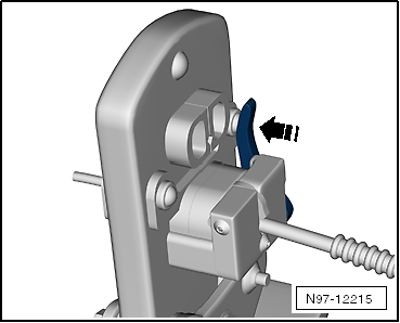
Transport Protection, Activating
- Close the Fiber-Optic Repair Set - Pliers -VAS6223/1-.
- Tighten the hex socket bolt -arrow- for the transport safety device on the cutter.
Attaching Brass Pin Contact to Fiber-Optic Cable
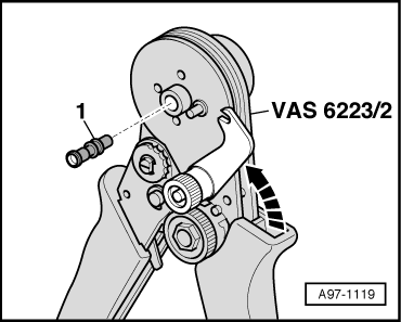
- Open securing lever on Fiber-Optic Repair Set - Crimping Pliers -VAS6223/2--arrow 1- and -arrow 2-.
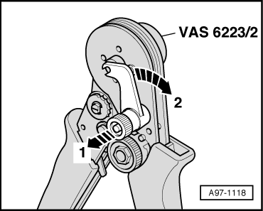
- Insert brass pin contact -1- in the mount.
- Close the safety lever on the Fiber-Optic Repair Set - Crimping Pliers -VAS6223/2--arrow-.
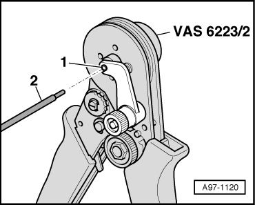
- Slide the fiber optic cable -2- into the brass pin contact -1- as far as spring-loaded stop.
- Slide fiber-optic cable further in up to fixed stop and close Fiber-Optic Repair Set - Crimping Pliers -VAS6223/2-.
- Open the crimping pliers for fiber-optic cable and remove the fiber-optic cable with the brass pin contact.
Caution
Do not bend the fiber-optic cable too much. The bending radius must be no less than 25 mm.
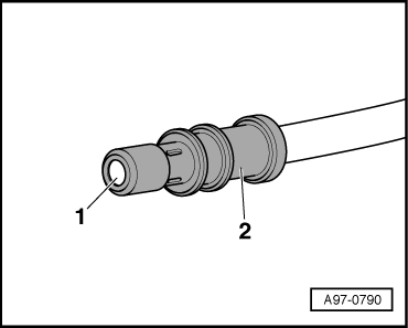
- Make sure the brass pin contact -2- is secured correctly on the fiber-optic cable -1-.
- Four crimp points must be visible at the brass connection pin.
- The brass pin contact must not be able to be removed by hand from the fiber-optic cable.
- The front surface of the fiber-optic cable is 0.01 to 0.1 mm behind the brass pin contact (visual check).
Note
- Connector couplings are available for connecting the fiber-optic cables. Refer to Parts Catalog.
- For installing the new fiber optic cable in the wiring harness connector. Refer to → Chapter "Fiber-Optic Cable, Disconnecting from Wiring Harness Connector".
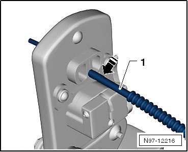
Corrugated Tube, Install on Fiber Optic Cable.
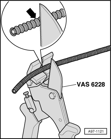
- Cut the corrugated tube to the appropriate length.
- Use the Hose Cutting Pliers -VAS6228- or a sharp knife for cutting.
- The corrugated tube must not be cut through using a side cutter under any circumstances
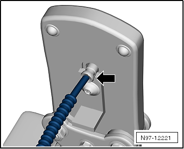
- The corrugated tube must be cut on the wave peak -arrow-, not in the wave trough.
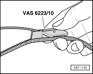
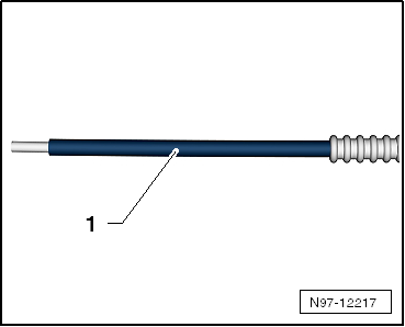
- Guide fiber-optic cable into Fiber-Optic Repair Set - Tube Tool -VAS6223/10- as shown in illustration.
- Position the crimping pliers for fiber-optic cable at the slot on the corrugated tube.
- Slide the crimping pliers for fiber-optic cable along the slot on the circumference of the corrugated tube. The fiber optic cable is then routed in the corrugated tube.
Fiber-Optic Cable, Preparing with the Fiber-Optic Conductor Repair Set -VAS6223A-
Special tools and workshop equipment required
- Fiber-Optic Conductor Repair Set -VAS6223A-
- Hose Cutting Pliers -VAS6228-
- Vehicle Diagnostic Tester
Caution
Do not bend the fiber-optic cable too much. The bending radius must be no less than 25 mm.
Fiber optic cables must not be routed over sharp edges.
The fiber-optic cable must not be dirty or touched with bare fingers.
Fiber optic cables may not be heated.
It is not permitted to twist together 2 fiber optic cables or one fiber optic cable with a copper wire.
Protect the connector and the connection box from dust. Place the cap on the trunk.
Mount Tool Head for the Fiber-Optic Repair Set - Pliers -VAS6223/1-.
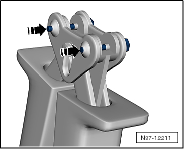
- Remove the locking pin -arrows-.
- Remove the tool set -arrow- and pull the locking pin back.
Fiber Optic Cable, Cutting to Length
- Establish length of fiber optic cable required.
- Open the Fiber-Optic Repair Set - Pliers and lay the fiber-optic cable -1- in the mount.
- Close the Fiber-Optic Repair Set - Pliers to cut the fiber-optic cable lengths.
Stripping
- Open the Fiber-Optic Repair Set - Pliers -VAS6223/1-.
- Position the wire stripper in the lower position -arrow-.
- Insert fiber-optic cable into the stripping station.
- The end of the fiber-optic cable must be flush with the rear side of the cutting pliers.
- Close the Fiber-Optic Repair Set - Pliers until the stop and keep closed.
- Bend the wire stripper upward -arrow- and remove the fiber-optic cable.
Precision Cutting (production of optical end face).
- Push the fiber-optic cable -1- into the cutting station.
- Insulation must make contact with cutting point stop.
- Close the Fiber-Optic Repair Set - Pliers -VAS6223/1- and remove the wire.
- Visually inspect the wire -1- to make sure that it was cut correctly and that there are no burrs on the front surface.
Note
- Fiber-optic cable is only to be placed on an absolutely clean surface or held in hand.
- Use the cap if there is a risk of the fiber-optic cable surface becoming dirty.
Attaching Brass Pin Contact to Fiber-Optic Cable.
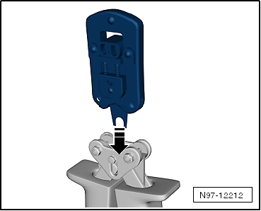
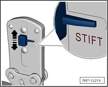
- Change tool head -arrow-.
- Slide the safeguard on the Fiber-Optic Repair Set - Pliers-arrow- so that the word "Stift" (pin) is legible.
- Insert a brass pin contact -1- in the mount.
- Close the securing lever on the Fiber-Optic Repair Set - Pliers-arrow-.
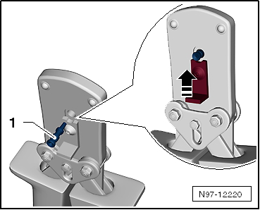
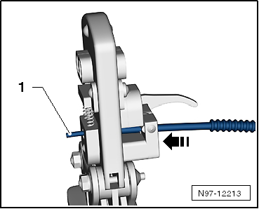
- Insert the fiber-optic cable into the brass pin contact -arrow- all the way up to the threaded stop and then close the Fiber-Optic Repair Set - Pliers.
- Open the fiber-optic cable pliers and remove the fiber-optic cable along with the brass contact pin.
Caution
Do not excessively bend or kink the fiber-optic cables (minimum bending radius 25 mm).
- Make sure the brass pin contact -2- is secured properly on the fiber-optic cable -1-.
- 4 crimped points must be visible on the brass connecting pin.
- The brass pin contact must not be able to be removed by hand from fiber-optic cable.
- The front surface of the fiber-optic cable is 0.01 to 0.1 mm behind the brass pin contact (visual check).
Note
- Connector couplings are available for connecting the fiber-optic cables. Refer to Parts Catalog.
- To install the new fiber optic cable in wiring harness connector. Refer to → Chapter "Fiber-Optic Cable, Disconnecting from Wiring Harness Connector".
Corrugated Tube, Install On Fiber Optic Cable
- Cut corrugated tube to appropriate length.
- Use the Hose Cutting Pliers -VAS6228- or a sharp knife for cutting.
- The corrugated tube must not be cut through using a side cutter under any circumstances
- The corrugated tube must be cut on the wave peak -arrow-, not in the wave trough.
- The corrugated tube must audibly engage in the fiber-optic cable housing when installing.
- Guide the fiber-optic cable into the Fiber-Optic Repair Set - Tube Tool -VAS6223/10- as shown.
- Position corrugated tube assembly pliers on slot on the tube.
- Position crimping pliers for fiber-optic cable at slot of corrugated tube. The fiber optic cable is then routed in the corrugated tube.
Fiber-Optic Cable, Disconnecting from Wiring Harness Connector
Removing
- Unplug connector for fiber optic cable from appropriate control unit.
- Release the catch in the fiber optic cable connector in direction of -arrow-.
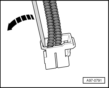
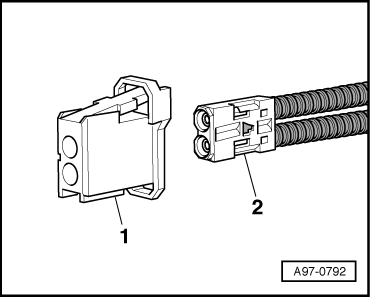
- Pull the fiber optic cable basic module -2- out of connector housing -1-.
Caution
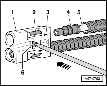
- Make colored dots to mark assignment of the fiber optic cable -5- to the corresponding sockets in the base module -1-.
- Note the arrows -3- for allocation on the base module "IN" and "OUT".
- Release the secondary catch -6- (blue pin) using a small screwdriver -arrow-.
- Release the catch -2- and remove the fiber-optic cable -5- with brass connector pin -4- from the base module -1-.
Installing
Install in reverse order of removal. Note the following:
Note
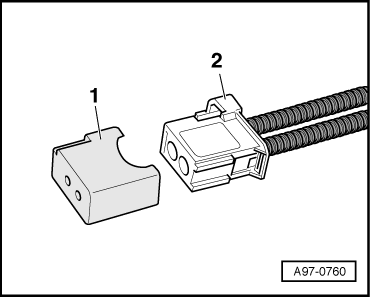
- Cover the open connector -2- for the fiber-optic cable using the Fiber-Optic Repair Set - Connector Protective Caps -VAS6223/9--1-.
- The protective cap prevents contamination of or mechanical damage to end face of fiber optic cable which would impair signal transmission.
- Install fiber optic cable in line with markings.
READ NEXT:
 Antenna Wires, Repairing
Aerial Cable Repair Set VAS6720
Special tools and workshop equipment required
Aerial Cable Repair Set -VAS6720-
The Aerial Cable Repair Set -VAS6720- makes it possible to
perform a quality repair
Connector Housings and Connectors, Repairing
Connector Housings and Connectors, Repair Information
Note
Observe general notes for repairs on the vehicle electrical
system. Refer to
→ Chapter "Vehicle Electrical System, General
Connector Housings, Releasing and Disassembling
Information on Releasing and Disassembling Connector Housings
Note
Observe general notes for repairs on the vehicle electrical
system. Refer to
→ Chapter "Vehicle Electrical System,
SEE MORE:
Safety Precautions
Safety Precautions when Working on Vehicles with Start/Stop System
There is a risk of injury due to the engine starting
unexpectedly.
The engine can start unexpectedly on vehicles with an activated
Start/Stop System. A message in the instrument cluster indicates
whether the Start/Stop System is a
Luggage Compartment Side Trim Panel, Removing and Installing
Luggage Compartment Side Trim Panel, Removing and Installing, Sedan
Special tools and workshop equipment required
Trim Removal Wedge -3409-
Pliers -T40172C-
Omega Clip Tool -T40280-
Removing
- Remove the side cushion. Refer to
→ Chapter "Side Cushion, Removing and Installing".
-&nb
