Audi A4: Battery Charger -VAS5095A-
 WARNING
Risk of injury. Follow all warning messages and safety precautions. Refer to → Chapter "Warnings and Safety Precautions".
In order to prevent damage to the Battery -A- or vehicle, observe the battery type information. Refer to → Chapter "Battery Types".
WARNING
Do not check or charge a Battery -A- when the visual indicator has "no color or is bright yellow". Jump starting must not be used!
There is a risk of explosion during testing, charging or jump starting.
These Batteries -A- must be replaced.
 Note
Note
- The charge current cannot be read on the Battery Charger -VAS5095A-. The charge current must be measured externally with a current probe (Test Instrument Set - Current Clamp - 100A -VAS6356/4A-).
- Observe the Battery Charger -VAS5095A- Operating Instructions.
- Battery Charger -VAS5095A- device description. Refer to → Chapter "Battery Charger -VAS5095A- Device Description".
- Charge the Battery -A-. Refer to → Chapter "Battery, Charging with Battery Charger -VAS5095A-".
- Severely discharged Battery -A-, charging. Refer to → Chapter "Severely Discharged Battery, Charging with Battery Charger -VAS5095A-".
- Support mode. Refer to → Chapter "Battery Charger -VAS5095A- Support Mode".
- Buffer mode/maintenance charging. Refer to → Chapter "Battery Charger -VAS5095A- Maintenance Charging".
Battery Charger -VAS5095A- Device Description
The Battery Charger -VAS5095A- is designed to charge all 12 V Batteries -A- in the VW group.
The battery is charged without amperage or voltage surges. Thereby the on-board electronics will not be affected. It is not necessary to remove the Battery -A- from the vehicle or be disconnected from the electrical system during charging.
Battery Charger -VAS5095A-
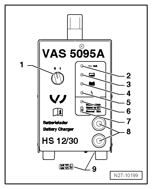
1 - ON/OFF-Switch (0 = OFF)
2 - Charge current display (I greater than 12 A)
3 - Battery -A- charge current display, partially charged (greater than 90%)
4 - Maintenance charging, lights up green when the Battery -A- is charged
5 - Interference indicator
6 - Support mode indicator
7 - Support mode/normal mode selector switch
8 - Charge cable: red charging clamp (+), black charging clamp (-)
9 - Battery type change switch (on the bottom of the unit)
Battery, Charging with Battery Charger -VAS5095A-
WARNING
Risk of injury. Follow all warning messages and safety precautions. Refer to → Chapter "Warnings and Safety Precautions".
Special tools and workshop equipment required
- Battery Charger -VAS5095A-
 Caution
While charging, always set the battery type to 2.4 V/C (Volts/Cell)! This applies to all Batteries -A-.
Note
The Battery -A- temperature must be at least 10 ºC.
WARNING
Do not check or charge a Battery -A- when the visual indicator has "no color or is bright yellow". Jump starting must not be used!
There is a risk of explosion during testing, charging or jump starting.
These Batteries -A- must be replaced.
Procedure
- Turn off the ignition and all electrical consumers and remove the ignition key.
- Check the battery type setting on the battery type switch. Refer to → Chapter "Battery Charger -VAS5095A- Device Description". The battery type switch must be set to 2.4V/C (Volts/Cell).
- Connect the red charge terminal (+) to the positive terminal of the Battery -A-.
Note
On vehicles with a Start/Stop function and an installed Battery Monitoring Control Module -J367-, the black charge terminal (-) must be connected to the body ground. The Start/Stop system will malfunction when it is connected to the Battery -A- negative terminal.
- Connect the black charge terminal (-) to the negative terminal of the Battery -A-/negative connector.
- Switch on the Battery Charger -VAS5095A-. Refer to → Chapter "Battery Charger -VAS5095A- Device Description".
Charge current displays. Refer to → Fig. " Battery Charger -VAS5095A- "-2- and -3- light up yellow. The Battery -A- is partially charged (approximately 90 %) when only the yellow LED -3- is on.
If the green LED. Refer to → Fig. " Battery Charger -VAS5095A- "-4- is also on, then the Battery Charger -VAS5095A- has switched to maintenance charging. The Battery -A- is charged.
- Switch off the Battery Charger -VAS5095A-. Refer to → Chapter "Battery Charger -VAS5095A- Device Description".
- Remove the charging clamps from the battery terminals.
Severely Discharged Battery, Charging with Battery Charger -VAS5095A-
WARNING
Risk of injury. Follow all warning messages and safety precautions. Refer to → Chapter "Warnings and Safety Precautions".
The Battery Charger -VAS5095A- automatically detects severely discharged Batteries -A- and starts the charging process conservatively with a low charge current. The charge current is automatically adjusted to the battery charge state.
Note
- For information in the chapter. Refer to → Chapter "Severely Discharged Batteries".
- The battery voltage must be at least 0.6 V!
- Severely discharged Batteries -A- in vehicles must be replaced prior to delivery. Pre-existing damage cannot be ruled out.
WARNING
Do not check or charge a Battery -A- when the visual indicator has "no color or is bright yellow". Jump starting must not be used!
There is a risk of explosion during testing, charging or jump starting.
These Batteries -A- must be replaced.
Procedure
- Charge the Battery -A-. Refer to → Chapter "Battery, Charging with Battery Charger -VAS5095A-".
Battery Charger -VAS5095A- Support Mode
General Information
The support mode provides the vehicle electrical system with voltage when the Battery -A- is removed or disconnected.
For more information. Refer to the Battery Charger -VAS5095A- Operating Instructions.
The support mode is used for the following situations:
- Vehicle electrical system support mode with the Battery -A- not installed
- Maintaining the voltage when the battery is being replaced
- Systems test without the Battery -A-
WARNING
Risk of injury. Follow all warning messages and safety precautions. Refer to → Chapter "Warnings and Safety Precautions".
WARNING
Do not check or charge a Battery -A- when the visual indicator has "no color or is bright yellow". Jump starting must not be used!
There is a risk of explosion during testing, charging or jump starting.
These Batteries -A- must be replaced.
Special tools and workshop equipment required
- Battery Charger -VAS5095A-
Procedure
Caution
- The polarity protection of the charger clamps is not active in the operation mode "charging severely discharged batteries/Support mode". Connect the charger clamps to the battery terminals correctly according to polarity!
- It can result in sparks due to short circuit.
- This constitutes an explosion risk.
- Make sure the charging clamp connections are secure.
- Remove the Battery -A-. Refer to → Electrical Equipment; Rep. Gr.27; Battery; Battery, Removing and Installing.
Caution
Whenever the Battery -A- is removed, be careful to prevent contact between the connected charge clamp on the positive terminal and the body ground. Likewise prevent contact between the battery terminals.
- Clamp the red charging clamp (+) to the vehicle positive battery terminal.
Note
On vehicles with a Start/Stop function and an installed Battery Monitoring Control Module -J367-, the black charge terminal (-) must be connected to the body ground. The Start/Stop system will malfunction when it is connected to the Battery -A- negative terminal.
- Attach the black charging clamp (-) to the vehicle battery negative terminal.
- Check the setting for the support mode/standard operation switch. Refer to → Chapter "Battery Charger -VAS5095A- Device Description". It must be set to "support mode".
- Check correct polarity connection of charger clamps.
- Switch on the Battery Charger -VAS5095A-. Refer to → Chapter "Battery Charger -VAS5095A- Device Description".
The Battery Charger -VAS5095A- starts the support mode.
End the Battery Support Mode
- Switch off the Battery Charger -VAS5095A-. Refer to → Chapter "Battery Charger -VAS5095A- Device Description".
- Remove the charging clamps from the battery terminals.
- Disconnect the Battery Charger -VAS5095A- from the power.
Battery Charger -VAS5095A- Maintenance Charging
WARNING
Risk of injury. Follow all warning messages and safety precautions. Refer to → Chapter "Warnings and Safety Precautions".
WARNING
Do not check or charge a Battery -A- when the visual indicator has "no color or is bright yellow". Jump starting must not be used!
There is a risk of explosion during testing, charging or jump starting.
These Batteries -A- must be replaced.
In maintenance charging, the Battery Charger -VAS5095A- provides safe charging and preserves the charge of the Battery -A-.
Procedure
- Proceed as if charging the Battery -A-. Refer to → Chapter "Battery, Charging with Battery Charger -VAS5095A-".
If the Battery -A- is discharged by an electrical consumer during maintenance charging, the Battery Charger -VAS5095A- automatically supplies the appropriate charge.
Maintenance charging can be performed without time restrictions. The Battery -A- can be used constantly.
READ NEXT:
 Battery Charger -VAS5900-
Battery Charger -VAS5900- Device Description
The Battery Charger -VAS5900- is designed to charge all 12 V
Batteries -A- in the VW group.
Battery Charger -VAS5900-
Control Field Overview
1 -&nb
Battery Charger -VAS5900- Service Charge
WARNING
Risk of injury. Follow all warning messages and
safety precautions. Refer to
→ Chapter "Warnings and Safety Precautions".
Caution
"Service charging" is not permitted
Battery Charger -VAS5900- Support Mode
General Information
The support mode provides the vehicle electrical system with
voltage when the Battery -A- is removed or disconnected.
For more information. Refer to the Battery Charger -VAS5900-
SEE MORE:
Traffic light information
Description
Applies to: vehicles with traffic light information
Fig. 105 Instrument cluster: traffic light information display
The traffic light information gives you a speed
recommendation in order to reach the next traffic
light when it is green (1), or it informs you of
the wait time at the ne
Refrigerant Circuit, Discharging with Service Station
Work procedure may vary depending on the type of tools
selected (the tool-specific operating instructions should
therefore be followed).
The refrigerant circuit is to be discharged if parts of the
refrigerant circuit are to be removed, if there is any doubt
about the quantity of refrigerant i
