Audi A4: Battery Charger -VAS5900- Service Charge
 WARNING
Risk of injury. Follow all warning messages and safety precautions. Refer to → Chapter "Warnings and Safety Precautions".
 Caution
"Service charging" is not permitted for VW vehicles, because voltage surges can damage the on-board electronics.
The Battery -A- must always be disconnected from the vehicle electrical system when using the "service charge" mode.
WARNING
Do not check or charge a Battery -A- when the visual indicator has "no color or is bright yellow". Jump starting must not be used!
There is a risk of explosion during testing, charging or jump starting.
These Batteries -A- must be replaced.
Caution
Always set the mode that corresponds to the Battery -A- during the charging process. Refer to the Battery Charger -VAS5900- Operating Instructions.
"Service Charging" is suitable for:
Wet batteries having a visual indicator which allows charging (visual indicator black or green).
The "Service charge (SERV)" mode is only used with sulfated Batteries -A-. The Battery -A- with voltages greater than 14.4 V is charged. A partial removal of the sulfation layer can result from this. Check the visual indicator after charging, immediately before the Battery -A- is used. Refer to → Chapter "Visual Indicator Color Display, Checking".
Special tools and workshop equipment required
- Battery Charger -VAS5900-
 Note
Note
The Battery -A- temperature must be at least 10 ºC (50 ºF).
Procedure
- Turn off the ignition and all electrical consumers and remove the ignition key.
- Connect the Battery Charger -VAS5900- to the power supply. The last selected mode is shown on the display. Refer to → Chapter "Battery Charger -VAS5900- Device Description".
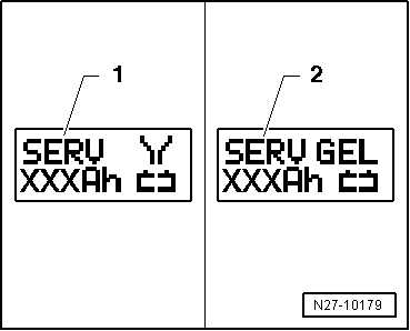
- Set the battery type with the INFO button.
The symbol -1- for "service charge of wet batteries" or the symbol -2- for "service charge of Gel/Absorbent Glass Mat (AGM) batteries" is indicated in the display.
- Set the battery capacity (Ah) on the Battery -A- to be charged with the corresponding ↑ button or ↓ button.
- Connect the red charge terminal (+) to the positive terminal of the Battery -A-.
Note
On vehicles with a Start/Stop function and an installed Battery Monitoring Control Module -J367-, the black charge terminal (-) must be connected to the body ground. The Start/Stop system will malfunction when it is connected to the Battery -A- negative terminal.
- Connect the black charge terminal (-) to the negative terminal of the Battery -A-/negative connector.
The Battery Charger -VAS5900- recognizes the nominal voltage of the connected Battery -A- (6 V/12 V/24 V) and begins the charging process automatically.
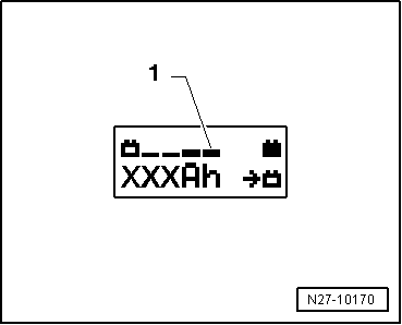
The Battery Charger -VAS5900- begins the "final charging" when the charge level is approximately 80 to 85 % of the battery voltage. The fourth bar is indicated on the display -1-. The Battery -A- is now ready to be used.
Note
A successful "service charge" depends on the degree of sulfation on the Battery -A-.
Possible malfunctions and how they are handled
1 - Displayed voltage does not match the nominal voltage:
- Hold down the ↑ button or ↓ button until the charging process begins.
2 - Displayed battery voltage does not match the nominal voltage - the charging process has already begun:
- Press the START/STOP button two times.
- Hold down the ↑ button or ↓ button until the charging process begins.
3 - The charger does not recognize a Battery -A-, when the battery voltage is less than 2 V:
The display remains unchanged.
The set operating mode and Ampere-hours (Ah) are displayed.
Battery -A- charging, ending
- Press the START/STOP-button.
- Remove the charging clamps from the battery terminals.
- Disconnect the Battery Charger -VAS5900- from the power.
Severely Discharged Battery, Charging with Battery Charger -VAS5900-
WARNING
Risk of injury. Follow all warning messages and safety precautions. Refer to → Chapter "Warnings and Safety Precautions".
WARNING
Do not check or charge a Battery -A- when the visual indicator has "no color or is bright yellow". Jump starting must not be used!
There is a risk of explosion during testing, charging or jump starting.
These Batteries -A- must be replaced.
Caution
- The polarity protection of the charger clamps is not active in the operation mode "charging severely discharged batteries/Support mode". Connect the charger clamps to the battery terminals correctly according to polarity!
- Always set the mode that corresponds to the Battery -A- during the charging process. Refer to the Battery Charger -VAS5900- Operating Instructions.
- The Battery Charger -VAS5900- does not recognize the severely discharged Battery -A-. Refer to → Chapter "Severely Discharged Batteries".
- Do not touch START / STOP button when battery cables are incorrectly connected! The Battery Charger -VAS5900- can become damaged.
The Battery Charger -VAS5900- will not automatically recognize the Battery -A- for Batteries -A- with a voltage less than 2 V.
Special tools and workshop equipment required
- Battery Charger -VAS5900-
Note
- For information in the chapter. Refer to → Chapter "Severely Discharged Batteries".
- The Battery -A- temperature must be at least 10 ºC (50 ºF).
- Severely discharged batteries in vehicles must be replaced prior to delivery. Pre-existing damage cannot be ruled out.
Procedure
- Turn off the ignition and all electrical consumers and remove the ignition key.
- Connect the Battery Charger -VAS5900- to the power supply. The last selected mode is shown on the display. Refer to → Chapter "Battery Charger -VAS5900- Device Description".
- Set the battery type with the INFO button.
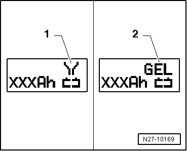
The symbol -1- for "service charge of wet batteries" or the symbol -2- for "service charge of Gel/Absorbent Glass Mat (AGM) batteries" is indicated in the display.
- Set the battery capacity (Ah) on the Battery -A- to be charged with the corresponding ↑ button or ↓ button.
- Connect the red charge terminal (+) to the positive terminal of the Battery -A-.
Note
On vehicles with a Start/Stop function and an installed Battery Monitoring Control Module -J367-, the black charge terminal (-) must be connected to the body ground. The Start/Stop system will malfunction when it is connected to the Battery -A- negative terminal.
- Connect the black charge terminal (-) to the negative terminal of the Battery -A-/negative connector.
- Press the START/STOP button for about 5 seconds. The menu selection "Charging severely discharged batteries/Support mode" is activated.
- Press the corresponding ↑-button or ↓ button to adjust the battery voltage(6 V/12 V/24 V).
Note
If no button is touched within five seconds, the Battery Charger -VAS5900- will return to the main menu (operating mode selection).
- Select the battery voltage by pressing the START/STOP button.
Then the inquiry about the correct polarity of the charging clamps is made.
- Check correct polarity connection of charger clamps.
- Confirm charging clamps are connected to correct poles via START/STOP button.
The Battery Charger -VAS5900- starts to charge the severely discharged Battery -A-.
Battery -A- charging, ending
- Press the START/STOP-button.
- Remove the charging clamps from the battery terminals.
- Disconnect the Battery Charger -VAS5900- from the power.
READ NEXT:
 Battery Charger -VAS5900- Support Mode
General Information
The support mode provides the vehicle electrical system with
voltage when the Battery -A- is removed or disconnected.
For more information. Refer to the Battery Charger -VAS5900-
Battery Charger -VAS5903-
WARNING
Risk of injury. Follow all warning messages and
safety precautions. Refer to
→ Chapter "Warnings and Safety Precautions".
WARNING
Do not check or charge a Battery -A
Refresh Charging with Battery Charger -VAS5903-
WARNING
Risk of injury. Follow all warning messages and
safety precautions. Refer to
→ Chapter "Warnings and Safety Precautions".
WARNING
Do not check or charge a Battery -A
SEE MORE:
Level Control System Sensor
Overview - Front Level Control System Sensor
1 - Bolt
9 Nm
2 - Front Level Control System Sensor
Left Front Level Control System Sensor -G78-
Right Front Level Control System Sensor -G289-
With coupling rod and retaining plate
Removing and installing. Refer to
→&nbs
Seat Belt Latch, Function Test
Seat Belt Latch, Checking
- Insert the belt tongue into the seat belt latch until it clicks
into place. Check whether the locking mechanism is properly
engaged by giving the seat belt webbing a firm jerk.
Replace the entire seat belt with the seat belt latch if the
belt tongue fails even o
