Audi A4: Battery Charger -VAS5903-
 WARNING
Risk of injury. Follow all warning messages and safety precautions. Refer to → Chapter "Warnings and Safety Precautions".
WARNING
Do not check or charge a Battery -A- when the visual indicator has "no color or is bright yellow". Jump starting must not be used!
There is a risk of explosion during testing, charging or jump starting.
These Batteries -A- must be replaced.
 Note
Note
Observe the Battery Charger -VAS5903- Operating Instructions.
- Battery Charger -VAS5903- device description. Refer to → Chapter "Battery Charger -VAS5903- Device Description".
- Charge the Battery -A-. Refer to → Chapter "Battery, Charging with Battery Charger -VAS5903-".
- Refresh charging. Refer to → Chapter "Refresh Charging with Battery Charger -VAS5903-".
- Severely discharged Battery -A-, charging. Refer to → Chapter "Severely Discharged Battery, Charging with Battery Charger -VAS5903-".
- Support mode. Refer to → Chapter "Battery Charger -VAS5903- Support Mode".
- Maintenance charging. Refer to → Chapter "Battery Charger -VAS5903- Maintenance Charging".
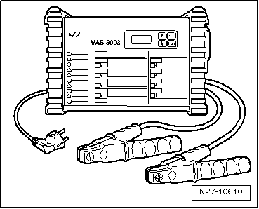
Battery Charger -VAS5903- Device Description
The Battery Charger -VAS5903- is designed to charge all 12 V Batteries -A- in the VW group.
Battery Charger -VAS5903-
Control Field Overview
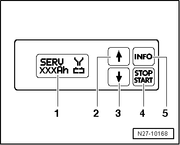
1 - Display
2 - ↑-button "Up"
3 - ↓-button "Down"
4 - START/STOP-button
5 - INFO-button
Battery, Charging with Battery Charger -VAS5903-
WARNING
Risk of injury. Follow all warning messages and safety precautions. Refer to → Chapter "Warnings and Safety Precautions".
WARNING
Do not check or charge a Battery -A- when the visual indicator has "no color or is bright yellow". Jump starting must not be used!
There is a risk of explosion during testing, charging or jump starting.
These Batteries -A- must be replaced.
Special tools and workshop equipment required
- Battery Charger -VAS5903-
Note
The Battery -A- temperature must be at least 10 ºC.
Procedure
- Turn off the ignition and all electrical consumers and remove the ignition key.
- Connect the Battery Charger -VAS5903- to the power supply. The last selected operation mode is shown on the display. Refer to → Chapter "Battery Charger -VAS5903- Device Description".
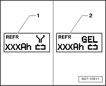
- Set the battery type with the INFO button.
The symbol -1- for "standard charge of wet batteries" or the symbol -2- for "standard charge of Gel/Absorbent Glass Mat (AGM) batteries" is indicated in the display.
- Set the battery capacity (Ah) on the Battery -A- to be charged with the corresponding ↑ button or ↓ button.
- Connect the red charge terminal (+) to the positive terminal of the Battery -A-.
Note
On vehicles with a Start/Stop function and an installed Battery Monitoring Control Module -J367-, the black charge terminal (-) must be connected to the body ground. The Start/Stop system will malfunction when it is connected to the Battery -A- negative terminal.
- Connect the black charge terminal (-) to the negative terminal of the Battery -A-/negative connector.
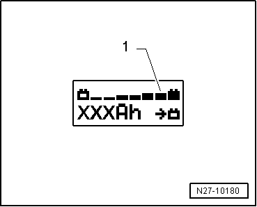
The Battery Charger -VAS5903- recognizes the nominal voltage of the connected Battery -A- (6 V/12 V/24 V) and begins the charging process automatically.
The Battery Charger -VAS5903- begins the "final charging" when the charge level is approximately 80 to 85%. The fourth bar is indicated on the display -1-. The Battery -A- is ready to be used.
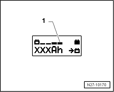
With a charge status of 100%, all bars are indicated on the display -1-.
Note
- With the battery type "standard charge", parallel operation of electrical consumers during the charging process is possible. The charging time is lengthened by this.
- Depending on the battery type, the Battery Charger -VAS5903- switches to maintenance charging after 1 to 7 hours. To reach a 100% charge level, the Battery -A- should remain connected to the Battery Charger -VAS5903-.
Possible malfunctions and how they are handled
1 - Displayed voltage does not match the nominal voltage:
- Hold down the ↑ button or ↓ button until the charging process begins.
2 - Displayed battery voltage does not match rated voltage - charging process has already begun:
- Press the START/STOP button two times.
- Hold down the ↑ button or ↓ button until the charging process begins again.
3 - The charger does not recognize a Battery -A-, when the battery voltage is less than 2 V:
The display remains unchanged.
The selected battery type and Ampere hours (Ah) are displayed.
Battery -A- charging, ending
- Press the START/STOP-button.
- Remove the charging clamps from the battery terminals.
- Disconnect the Battery Charger -VAS5903- from the power.
READ NEXT:
 Refresh Charging with Battery Charger -VAS5903-
WARNING
Risk of injury. Follow all warning messages and
safety precautions. Refer to
→ Chapter "Warnings and Safety Precautions".
WARNING
Do not check or charge a Battery -A
Battery Charger -VAS5903- Support Mode
General Information
The support mode provides the vehicle electrical system with
voltage when the Battery -A- is removed or disconnected.
For more information. Refer to the Battery Charger -VAS5903-
Battery Charger -VAS5906-
WARNING
Risk of injury. Follow all warning messages and
safety precautions. Refer to
→ Chapter "Warnings and Safety Precautions".
WARNING
Do not check or charge a Battery -A
SEE MORE:
Rear Lid, Removing and Installing
Rear Lid, Removing and Installing, Sedan
To complete the procedure, a second technician is required to be at
the following position.
Removing
- Remove the rear lid lower trim panel. Refer to
→ Body Interior; Rep. Gr.70; Luggage Compartment Trim Panels;
Rear Lid Lower Trim
Center Console, Removing and Installing
Removing
- Remove the front footwell center console trim panel. Refer to
→ Chapter "Front Footwell Center Console Trim Panel, Removing
and Installing".
- Remove the front center console storage compartment. Refer to
→ Chapter "Front Storage Compartment, Removing and Installi
