Audi A4: Battery Charger -VAS5903- Support Mode
General Information
The support mode provides the vehicle electrical system with voltage when the Battery -A- is removed or disconnected.
For more information. Refer to the Battery Charger -VAS5903- Operating Instructions.
The support mode is used for the following situations:
- Vehicle electrical system support mode with the Battery -A- not installed
- Maintaining the voltage when the battery is being replaced
- Systems test without the Battery -A-
 WARNING
Risk of injury. Follow all warning messages and safety precautions. Refer to → Chapter "Warnings and Safety Precautions".
WARNING
Do not check or charge a Battery -A- when the visual indicator has "no color or is bright yellow". Jump starting must not be used!
There is a risk of explosion during testing, charging or jump starting.
These Batteries -A- must be replaced.
Special tools and workshop equipment required
- Battery Charger -VAS5903-
Procedure
 Caution
- The polarity protection of the charger clamps is not active in the operation mode "charging severely discharged batteries/Support mode". Connect the charger clamps to the battery terminals correctly according to polarity!
- It can result in sparks due to short circuit.
- This constitutes an explosion risk.
- Make sure the charging clamp connections are secure.
- Do not touch START / STOP button when battery cables are incorrectly connected! The Battery Charger -VAS5903- can become damaged.
- Remove the Battery -A-. Refer to → Electrical Equipment; Rep. Gr.27; Battery; Battery, Removing and Installing.
- Connect the Battery Charger -VAS5903- to the power supply. The last selected operation mode is shown on the display. Refer to → Chapter "Battery Charger -VAS5903- Device Description".
Caution
Whenever the Battery -A- is removed, be careful to prevent contact between the connected charge clamp on the positive terminal and the body ground. Likewise prevent contact between the battery terminals.
- Connect the red charge terminal (+) to the positive terminal of the Battery -A-.
 Note
Note
On vehicles with a Start/Stop function and an installed Battery Monitoring Control Module -J367-, the black charge terminal (-) must be connected to the body ground. The Start/Stop system will malfunction when it is connected to the Battery -A- negative terminal.
- Connect the black charge terminal (-) to the negative terminal of the Battery -A-/negative connector.
- Press the START/STOP button for about 5 seconds. The menu selection "Charging severely discharged batteries/Support mode" is activated.
- Press the corresponding ↑-button or ↓ button to adjust the battery voltage(6 V/12 V/24 V).
Note
If no button is touched within five seconds, the Battery Charger -VAS5903- will return to the main menu (operating mode selection).
- Select the battery voltage by pressing the START/STOP button.
Then the inquiry about the correct polarity of the charging clamps is made.
- Check correct polarity connection of charger clamps.
- Confirm charging clamps are connected to correct poles via START/STOP button.
The Battery Charger -VAS5903- starts the Battery -A- support mode.
End the Battery Support Mode
- Press the START/STOP-button.
- Remove the charging clamps from the battery terminals.
- Disconnect the Battery Charger -VAS5903- from the power.
Battery Charger -VAS5903- Maintenance Charging
Note
- If the Battery -A- is discharged by an electrical consumer during maintenance charging, the Battery Charger -VAS5903- automatically supplies an appropriate charge.
- Maintenance charging can be performed without time restrictions.
- The Battery -A- can be used constantly.
- Observe the maintenance notes of the battery manufacturer.
WARNING
Risk of injury. Follow all warning messages and safety precautions. Refer to → Chapter "Warnings and Safety Precautions".
WARNING
Do not check or charge a Battery -A- when the visual indicator has "no color or is bright yellow". Jump starting must not be used!
There is a risk of explosion during testing, charging or jump starting.
These Batteries -A- must be replaced.
Special tools and workshop equipment required
- Battery Charger -VAS5903-
If the Battery -A- is fully charged, the Battery Charger -VAS5903- starts maintenance charging.
Procedure
- Proceed as if charging the Battery -A-. Refer to → Chapter "Battery, Charging with Battery Charger -VAS5903-".
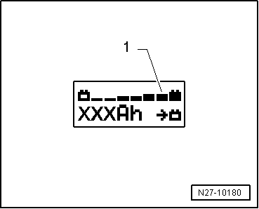
With a charge status of 100%, all bars are indicated on the display -1-.
READ NEXT:
 Battery Charger -VAS5906-
WARNING
Risk of injury. Follow all warning messages and
safety precautions. Refer to
→ Chapter "Warnings and Safety Precautions".
WARNING
Do not check or charge a Battery -A
Solar Battery Maintainer -VAS6102A-
Solar Battery Maintainer -VAS6102A- Device Description
Solar Battery Maintainer -VAS6102A-
The Solar Battery Maintainer -VAS6102A- supports the vehicle
electrical system and prevents the Battery -A-
Generator
Generator, Checking
Perform Generator Test
Vehicle Diagnostic Tester is attached.
- Select the Diagnostic mode and
start the diagnostics.
- Select the tab Test Plan.
- Select Select In
SEE MORE:
Vehicle Interior Trim Panels
Component Location Overview - Vehicle Interior Trim Panels
Component Location Overview - Vehicle Interior Trim Panels, A3 Sedan
1 - D-Pillar Trim Panel
Overview. Refer to
→ Chapter "Overview - D-Pillar Trim Panel".
2 - C-Pillar Trim Panel
Overview. Refer to
→&nbs
Tire pressure monitoring
system
General notes
Each tire, including the spare (if provided),
should be checked monthly when cold and inflated
to the inflation pressure recommended by the
vehicle manufacturer on the vehicle placard or
tire inflation pressure label. (If your vehicle has
tires of a different size than the size indica
