Audi A4: Generator
Generator, Checking
Perform Generator Test
Vehicle Diagnostic Tester is attached.
- Select the Diagnostic mode and start the diagnostics.
- Select the tab Test Plan.
- Select Select Individual Tests and choose the following sequence.
- Body
- Electrical Equipment
- 27 - Starter, voltage supply
- Electrical Components
- C - Generator, Checking
The Vehicle Diagnostic Tester continues with the generator test from here on.
Overview - Generator, Bosch through MY 2000
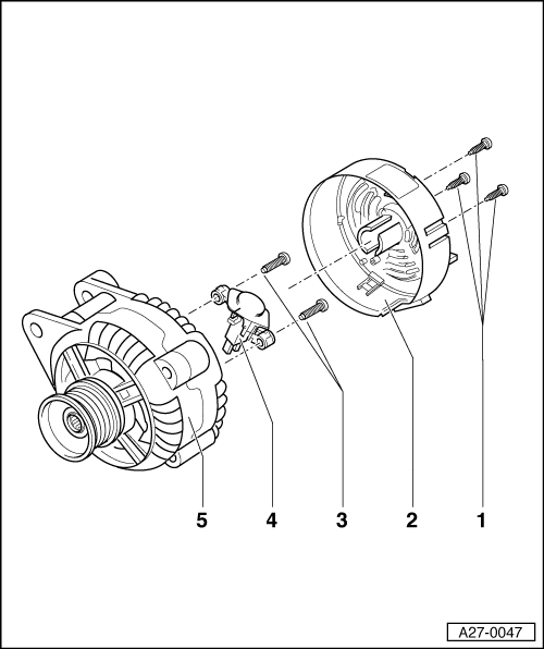
1 - Bolts
- 1 Nm
2 - Cover
- With three tabs
3 - Bolts
- 2 Nm
4 - Voltage Regulator
- Removing:
- Remove the bolts -1- and remove the protective cap -2-.
- Remove the bolts -3- and remove the voltage regulator.
- Carbon brushes wear limit: 5 mm
5 - Generator
Overview - Bosch Generator from 2001
 Note
Note
The generators were implemented as a running change.
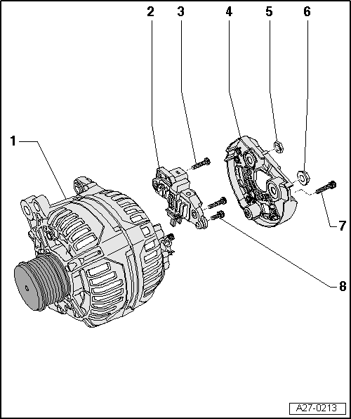
1 - Generator
2 - Voltage Regulator
- Removing and installing. Refer to → Chapter "Voltage Regulator, Bosch Generator from 2001, Removing and Installing".
- Carbon brushes, checking. Refer to → Chapter "Carbon Brushes, Checking, All Bosch Generators from 2001"
3 - Bolt
- 2.5 Nm
4 - Cover
5 - Nut
- 12 Nm
6 - Nut
- 30 Nm
7 - Bolt
- 3 Nm
8 - Bolt
- 1.5 Nm
READ NEXT:
 Voltage Regulator, Bosch Generator from 2001, Removing and Installing
Removing
- Remove the generator. Refer to
→ Electrical Equipment; Rep. Gr.27; Generator; Generator,
Removing and Installing.
- Remove the bolt -1- and the
nuts -3- and
-
Voltage Regulator, Valeo Generator from 2001, Removing and Installing
Removing
- Remove the generator. Refer to
→ Electrical Equipment; Rep. Gr.27; Generator; Generator,
Removing and Installing.
- Press the cover on the rear side of the gene
Ribbed Belt Pulley without Freewheel, Removing and Installing
Special tools and workshop equipment required
Generator Belt Socket -3310-
Inner hex socket 8 mm or TORX
T50
Removing
- Remove the generator if necessary. Refer to
→ Electrical Equipm
SEE MORE:
Battery
Battery general information
Because of the complex power supply, all work
on batteries such as disconnecting, replacing,
etc., should only be performed by an authorized
Audi dealer or authorized Audi Service Facility.
Multiple batteries with different technologies
may be installed in your vehicle:
Specified Values for the Refrigerant Circuit Pressures
Note
On vehicles with a high-voltage system but without a heat
pump (for example on Audi A3 e-tron, Audi Q5 hybrid, Audi A6
hybrid and Audi A8 hybrid) no check valves are installed in the
refrigerant circuit. On these vehicles valves are installed in
the refrigerant circuit which regulat
© 2019-2026 Copyright www.audia4b9.com
