Audi A4: Level Control System Sensor
Overview - Front Level Control System Sensor
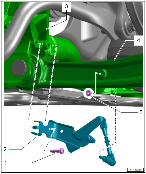
1 - Bolt
- 9 Nm
2 - Front Level Control System Sensor
- Left Front Level Control System Sensor -G78-
- Right Front Level Control System Sensor -G289-
- With coupling rod and retaining plate
- Removing and installing. Refer to → Chapter "Left/Right Front Level Control System Sensor -G78-/-G289-, Removing and Installing".
- Installation position: sensor coupling rod points outward
3 - Subframe
4 - Control Arm
5 - Nut
- 9 Nm
- Replace after removing
- Self-locking
Overview - Rear Level Control System Sensor
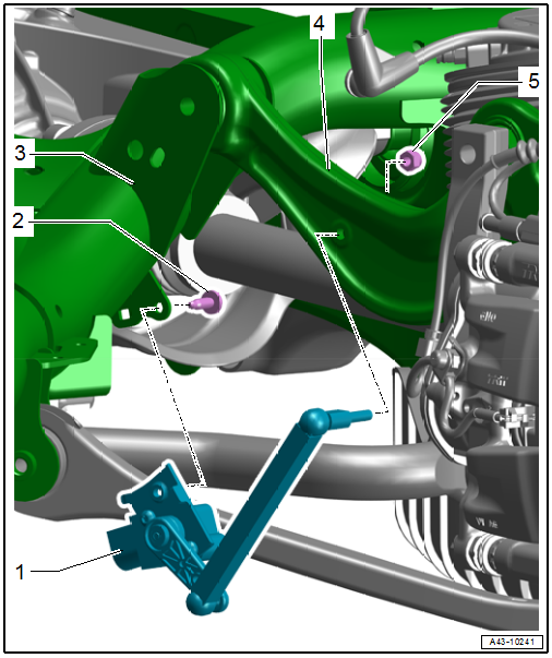
1 - Rear Level Control System Sensor
- Left Rear Level Control System Sensor -G76-
- Right Rear Level Control System Sensor -G77-
- With coupling rod and retaining plate
- Removing and installing. Refer to → Chapter "Left/Right Rear Level Control System Sensor -G76-/-G77-, Removing and Installing".
- Installation position: Sensor coupling rod points toward the rear
2 - Bolt
- 9 Nm
3 - Subframe
4 - Front Upper Transverse Link
5 - Nut
- 9 Nm
- Replace after removing
- Self-locking
Left/Right Front Level Control System Sensor -G78-/-G289-, Removing and Installing
Special tools and workshop equipment required
- Torque Wrench 1410 -VAG1410-
 Caution
This procedure contains mandatory replaceable parts. Refer to component overview and parts catalog prior to starting procedure.
Mandatory Replacement Parts
- Nut - Front Level Control System Sensor to Subframe
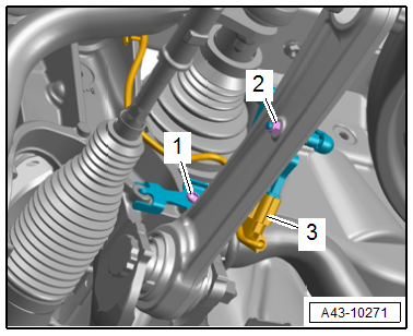
Removing
- Disconnect the connector -3- and free up the wire.
- Remove the coupling rod nut -2-.
- Remove the bolt -1- and remove the level control system sensor
Installing
Install in reverse order of removal and note the following:
- Adjust the headlamps. Refer to → Electrical Equipment; Rep. Gr.94; Headlamps; Headlamps, Adjusting.
- Driver assistance systems front camera, calibrating. Refer to → Chapter "Driver Assistance Systems Front Camera, Calibrating".
Tightening Specifications
- Refer to → Chapter "Overview - Front Level Control System Sensor"
Left/Right Rear Level Control System Sensor -G76-/-G77-, Removing and Installing
Special tools and workshop equipment required
- Torque Wrench 1410 -VAG1410-
Caution
This procedure contains mandatory replaceable parts. Refer to component overview and parts catalog prior to starting procedure.
Mandatory Replacement Parts
- Nut - Rear Level Control System Sensor to Front Upper Transverse Link
Removing
- Disconnect the connector -3-.
- Remove the coupling rod nut -1-.
- Remove the bolt -2- and remove the level control system sensor.
Installing
Install in reverse order of removal and note the following:
- Adjust the headlamps. Refer to → Electrical Equipment; Rep. Gr.94; Headlamps; Headlamps, Adjusting.
Tightening Specifications
- Refer to → Chapter "Overview - Rear Level Control System Sensor"
Special Tools
Special tools and workshop equipment required
- Torque Wrench 1410 -VAG1410-
READ NEXT:
 Axle Alignment Information
Wheel alignment must only performed using VW/Audi-approved
alignment equipment.
Each time wheels are aligned, both front and rear wheels
must be aligned. Otherwise, the correct driving handling of t
SEE MORE:
Traffic jam assist
Description
Applies to: vehicles with traffic jam assist
Fig. 116 Turn signal lever: button for traffic jam assist and
Audi active lane assist
Traffic jam assist supports the driver when driving
in traffic jams or in heavy traffic.
In a speed range under 40 mph (65 km/h), the
system can help to
ESD Work Surface -VAS6613-
The electro-static discharge ESD Work Surface -VAS6613-
protect electronic components from getting damaged by an
electro-static charge.
This makes is possible to perform repairs on sensitive
electronic components on an open mat.
For more information as to what work can be performed on the
ES
