Audi A4: Exhaust System, Emissions Controls
Exhaust Pipes/Mufflers
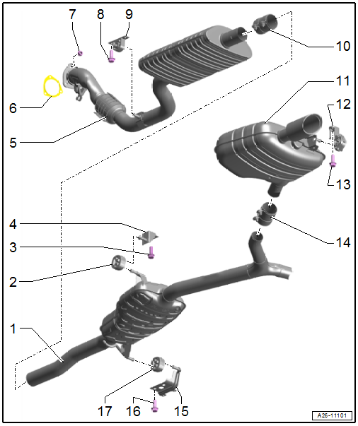
Overview - Muffler
Overview - Muffler, FWD Vehicle
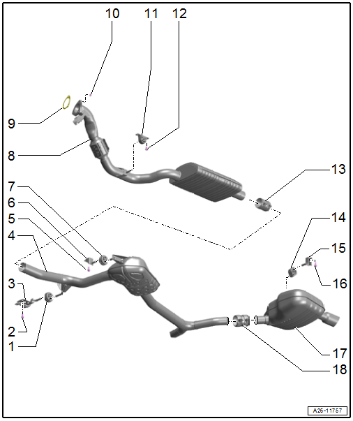
1 - Retaining Loop
- Replace if damaged
- Exhaust system, installing without tension. Refer to → Chapter "Exhaust System, Installing without Tension".
2 - Bolt
- 23 Nm
3 - Bracket
4 - Center Muffler
- Original equipment as one unit with the rear muffler. If a repair is required replace each separately
- Separating point. Refer to → Chapter "Exhaust Pipes/Mufflers, Disconnecting".
- Exhaust system, installing without tension. Refer to → Chapter "Exhaust System, Installing without Tension".
5 - Bolt
- 23 Nm
6 - Bracket
7 - Retaining Loop
- Replace if damaged
- Exhaust system, installing without tension. Refer to → Chapter "Exhaust System, Installing without Tension".
8 - Front Muffler
- With a coupling
 Caution
Risk of damaging the coupling.
- Coupling must not be bent more than 10º.
- Do not load the coupling on the cable.
- Do not damage the wire mesh on the coupling.
- Removing and installing. Refer to → Chapter "Front Muffler, Removing and Installing".
- Exhaust system, installing without tension. Refer to → Chapter "Exhaust System, Installing without Tension".
9 - Seal
- Replace after removing
10 - Nut
- 23 Nm
11 - Mount
- Equipped on some models
- Replace if damaged
- Check the pretension. Refer to → Chapter "Exhaust System, Installing without Tension".
12 - Bolt
- 23 Nm
13 - Front Clamping Sleeve
- Before tightening, align the exhaust system without tension. Refer to → Chapter "Exhaust System, Installing without Tension".
- Installation position. Refer to → Fig. "Front Clamping Sleeve - Installation Position".
- Tighten the threaded connections equally to 23 Nm.
14 - Retaining Loop
- Replace if damaged
- Exhaust system, installing without tension. Refer to → Chapter "Exhaust System, Installing without Tension".
15 - Bracket
16 - Bolt
- 23 Nm
17 - Rear Muffler
- Original equipment one unit with the center muffler. If a repair is required replace each separately
- Separating point. Refer to → Chapter "Exhaust Pipes/Mufflers, Disconnecting".
- Exhaust system, installing without tension. Refer to → Chapter "Exhaust System, Installing without Tension".
18 - Rear Clamping Sleeve
- Before tightening, align the exhaust system without tension. Refer to → Chapter "Exhaust System, Installing without Tension".
- Installation position. Refer to → Fig. "Rear Clamping Sleeve - Installation Position".
- Tighten the threaded connections equally to 23 Nm.
Individual Mounting Components for Front Muffler
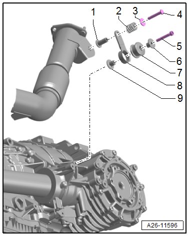
1 - Spacer Sleeve
2 - Pressure Spring
3 - Washer
4 - Bolt - 23 Nm
5 - Bolt - 23 Nm
6 - Spacer Sleeve
7 - Buffer
8 - Tab
9 - Spacer Sleeve
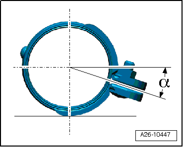
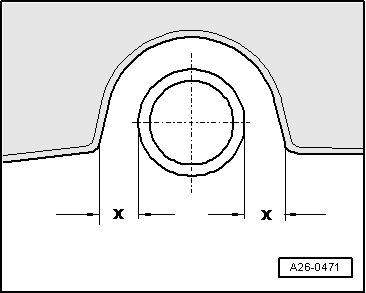
Front Clamping Sleeve - Installation Position
- Install the clamping sleeve in the position shown.
- Angle -α- = approximately 20º.
- The threaded connections are to the right.
- Nuts downward.
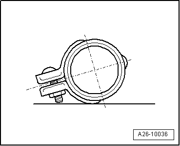
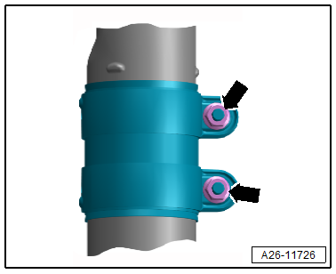
Rear Clamping Sleeve - Installation Position
- Install the clamping sleeve in the position shown.
- Threaded connections are to the left.
- Nuts downward.
- Bolt ends must not protrude over the lower edge of the clamping sleeve.
Overview - Muffler, AWD Vehicles
1 - Center Muffler
- Original equipment as one unit with rear mufflers. If a repair is required replace each separately
- Separating point. Refer to → Chapter "Exhaust Pipes/Mufflers, Disconnecting".
- Exhaust system, installing without tension. Refer to → Chapter "Exhaust System, Installing without Tension".
2 - Retaining Loop
- Replace if damaged
- Exhaust system, installing without tension. Refer to → Chapter "Exhaust System, Installing without Tension".
3 - Bolt
- 23 Nm
4 - Bracket
5 - Front Muffler
- With a coupling
Caution
Risk of damaging the coupling.
- Coupling must not be bent more than 10º.
- Do not load the coupling on the cable.
- Do not damage the wire mesh on the coupling.
- Removing and installing. Refer to → Chapter "Front Muffler, Removing and Installing".
- Exhaust system, installing without tension. Refer to → Chapter "Exhaust System, Installing without Tension".
6 - Seal
- Replace after removing
7 - Nut
- 23 Nm
8 - Bolt
- 23 Nm
9 - Mount
- Replace if damaged
- Check the pretension. Refer to → Chapter "Exhaust System, Installing without Tension".
10 - Front Clamping Sleeve
- Before tightening, align the exhaust system without tension. Refer to → Chapter "Exhaust System, Installing without Tension".
- Installation position. Refer to → Fig. "Front Clamping Sleeve - Installation Position".
- Tighten the threaded connections equally to 23 Nm.
11 - Rear Muffler
- Original equipment one unit with the center muffler. If a repair is required replace each separately
- Separating point. Refer to → Chapter "Exhaust Pipes/Mufflers, Disconnecting".
- Exhaust system, installing without tension. Refer to → Chapter "Exhaust System, Installing without Tension".
12 - Mount
- Replace if damaged
- Check the pretension. Refer to → Chapter "Exhaust System, Installing without Tension".
13 - Bolt
- 23 Nm
14 - Rear Clamping Sleeve
- Before tightening, align the exhaust system without tension. Refer to → Chapter "Exhaust System, Installing without Tension".
- Installation position. Refer to → Fig. "Rear Clamping Sleeve - Installation Position".
- Tighten the threaded connections equally to 23 Nm.
15 - Bracket
16 - Bolt
- 23 Nm
17 - Retaining Loop
- Replace if damaged
- Exhaust system, installing without tension. Refer to → Chapter "Exhaust System, Installing without Tension".
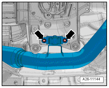
Exhaust Pipes/Mufflers, Disconnecting
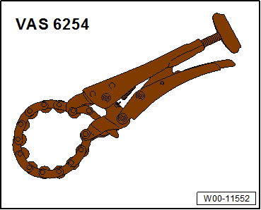
Special tools and workshop equipment required
- Chain Pipe Cutter -VAS6254-
- A separating point has been provided in the connecting pipe for individual replacement of the center or rear muffler.
- The separating point is marked by an indentation around the circumference of the exhaust pipe.
Procedure
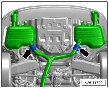
- Separate the exhaust pipes at a right angle at the notch -arrow- using a -VAS6254-.
- When installing, position the clamping sleeves -arrows- on the center of the separation cut.
- Install the clamping sleeves. Refer to → Fig. "Rear Clamping Sleeve - Installation Position".
- Install the exhaust system without tension. Refer to → Chapter "Exhaust System, Installing without Tension".
Tightening Specifications
- Refer to → Chapter "Overview - Muffler"
Front Muffler, Removing and Installing
Caution
This procedure contains mandatory replaceable parts. Refer to component overview and parts catalog prior to starting procedure.
Mandatory Replacement Parts
- Seal - Front Muffler
Removing
- Remove the engine cover. Refer to → Servicing - 4-Cylinder 2.0L 4V TFSI Engine; Rep. Gr.10; Engine Cover; Engine Cover, Removing and Installing.
- Remove the nuts -1- from the front muffler accessible from the top.
- Remove the rear noise insulation. Refer to → Body Exterior; Rep. Gr.66; Noise Insulation; Overview - Noise Insulation.
- Remove the nut -2- and bolt -3- for the front muffler.
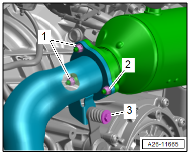
- Remove the front muffler bolts -arrows-.
- Loosen the clamping sleeve -arrows- and push toward the rear.
Caution
Risk of damaging the coupling.
- Coupling must not be bent more than 10º.
- Do not load the coupling on the cable.
- Do not damage the wire mesh on the coupling.
- Remove the front muffler.
Installing
Install in reverse order of removal and note the following:
 Note
Note
Replace seals and self-locking nuts after disassembly.
- Install the exhaust system without tension. Refer to → Chapter "Exhaust System, Installing without Tension".
- Install the engine cover. Refer to → Servicing - 4-Cylinder 2.0L 4V TFSI Engine; Rep. Gr.10; Engine Cover; Engine Cover, Removing and Installing.
Tightening Specifications
- Refer to → Chapter "Overview - Muffler"
- Refer to → Body Exterior; Rep. Gr.66; Noise Insulation; Overview - Noise Insulation.
Muffler, Removing and Installing
Removing
- Equipped on some models: remove the left and right diagonal brace. Refer to → Body Exterior; Rep. Gr.66; Underbody Trim Panel; Underbody Trim Panels, Removing and Installing.
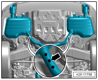
- Loosen the clamping sleeve -arrows- and push toward the rear.
Caution
Risk of damaging the couplings in the front muffler.
Do not bend couplings in front muffler more than 10º.
- Slightly lower the front muffler and remove the clamping sleeve.
- Tie up the front muffler.
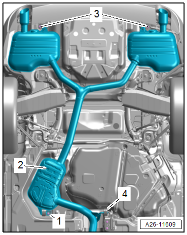
FWD Vehicle
 WARNING
Risk of accident due to the weight of the muffler.
A second technician is needed to remove the rear muffler.
- Disengage the mounting -4- from the exhaust system.
- Remove the bolts -1 and 3- and remove the muffler -2-.
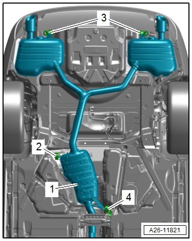
AWD Vehicles
WARNING
Risk of accident due to the weight of the muffler.
A second technician is needed to remove the rear muffler.
- Disengage the mounting -2 and 4- from the exhaust system.
- Remove the bolts -3- and remove the muffler -1-.
Installing
Install in reverse order of removal and note the following:
- Install the exhaust system without tension. Refer to → Chapter "Exhaust System, Installing without Tension".
Tightening Specifications
- Refer to → Chapter "Overview - Muffler"
- Refer to → Body Exterior; Rep. Gr.66; Underbody Trim Panel; Component Location Overview - Trim Panels.
Exhaust System, Installing without Tension
Procedure
- Align the exhaust system when cold.
- Loosen the front clamping sleeve -arrows-.
- Push the exhaust system far enough forward -arrow- until the pretension on the retaining loop -1- at the exhaust pipe is -a- = 6 to 10 mm.
- Position the front clamping sleeve (refer to → Fig. "Front Clamping Sleeve - Installation Position") and tighten the threaded connections evenly.
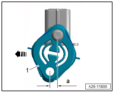
- Check the distance of left and right tail pipes to bumper:
- Dimension -x- left = dimension -x- right.
Tightening Specifications
- Refer to → Chapter "Overview - Muffler"
Exhaust System, Checking for Leaks
All procedures are described under: → Servicing - 4-Cylinder 2.0L 4V TFSI Engine; Rep. Gr.26; Exhaust Pipes/Mufflers; Exhaust System, Checking for Leaks.
Emissions Control System
All procedures and components are described under: → Servicing - 4-Cylinder 2.0L 4V TFSI Engine; Rep. Gr.26; Emissions Control System.
Special Tools
Special tools and workshop equipment required
- Chain Pipe Cutter -VAS6254-
Ignition/Glow Plug System
Ignition System
All procedures and components are described under: → Servicing - 4-Cylinder 2.0L 4V TFSI Engine; Rep. Gr.28; Ignition System.
Revision History
DRUCK NUMBER: A005A013621
.png)
READ NEXT:
 Warnings when Working on Vehicles with High Voltage System
Vehicles with a High-Voltage System (Hybrid Vehicles)
Working on Vehicles with High-Voltage System (Hybrid Vehicles)
Extremely Dangerous Due to High-Voltage
The high-voltage system is under high-volta
SEE MORE:
Fuel
Types of gasoline
The correct gasoline grade is stated on the inside
of the fuel filler door.
The vehicle is equipped with a catalytic converter
and must only be driven with unleaded gasoline.
Audi recommends using TOP TIER Detergent Gasoline.
For additional information on TOP TIER Detergent
Gasol
Audi pre sense front
Applies to: vehicles with Audi pre sense front
Audi pre sense front provides the same scope of
functions as Audi pre sense city, with a few exceptions. The system has an
extensive
field of view due to additional sensors that
are installed. Because of this, vehicles that are
braking or traveling sig
