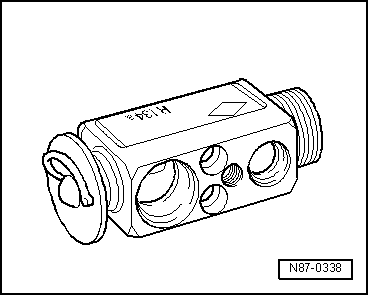
Audi A4: Expansion Valve
The expansion valve atomizes the streaming refrigerant and controls the flow quantity so that the vapor is gaseous only at the evaporator outlet, depending on the heat transmission.
 Note
Note
- Be sure to use the correct part number when replacing the expansion valve. Refer to the Parts Catalog.
- Different characteristic curves matched to the appropriate circuit. Refer to → Heating, Ventilation and Air Conditioning; Rep. Gr.87; System Overview - Refrigerant Circuit (vehicle-specific repair manual) and the Parts Catalog.
- Depending on the A/C compressor version, there may be a valve installed on the high pressure side of the A/C compressor, which prevents the liquid refrigerant from flowing back into the compressor once the A/C is turned off. If an A/C compressor with this valve is installed in a vehicle with a refrigerant circuit having an expansion valve, then it may take some time until the pressure in the high pressure side decreases (the expansion is cold and the pressure in the low pressure side quickly increases after it is turned off, the expansion valve closes and the refrigerant flows slowly into the low pressure side). If the A/C compressor is switched on, the pressure on the low pressure side goes down, the expansion valve open and the refrigerant can flow of the low pressure side.
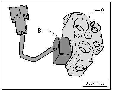
Expansion Valve with Shut-Off Valve
Note
There are different versions of the shut-off valve with different functions and with different names. The following illustrated Hybrid Battery Refrigerant Shut-Off Valve 2 -N517- is for example installed on an Audi Q7 hybrid in the battery cooling module. Refer to → Heating, Ventilation and Air Conditioning; Rep. Gr.87; Refrigerant Circuit; System Overview - Refrigerant Circuit.
- The expansion valve -A- with the Hybrid Battery Refrigerant Shut-Off Valve 2 -N517--B- atomizes the streaming refrigerant and regulates the refrigerant flow rate to the evaporator in the battery cooling module for the Hybrid Battery Unit -AX1- so that the vapor becomes gaseous only at the evaporator output, depending on the heat transmission.
- If the Hybrid Battery Refrigerant Shut-Off Valve 2 -N517--B- is activated by the electronics and is open, it lets refrigerant flow through the expansion valve -A- to the evaporator in the battery cooling module.
- The expansion valve -A- with the Hybrid Battery Refrigerant Shut-Off Valve 2 -N517--B- is installed on vehicles with a battery cooling module. It is activated when the A/C system is in operation, if it is necessary to cool the Hybrid Battery Unit -AX1-.
- If the Hybrid Battery Refrigerant Shut-Off Valve 2 -N517--B- is activated by the electronics (for example, by the Battery Regulation Control Module -J840-), it is open and lets the refrigerant flow according to its control characteristic toward the evaporator in the battery cooling module.
- The Hybrid Battery Refrigerant Shut-Off Valve 2 -N517--B- attached to the expansion valve -A- is activated, for example, by the Battery Regulation Control Module -J840-. Refer to → Wiring diagrams, Troubleshooting & Component locations. Use the Vehicle Diagnostic Tester in the "Guided Fault Finding" Function for the A/C System and the Battery Regulation.
- If, for a vehicle with two evaporators (one in the A/C unit and one in the battery cooling module, for example on the Q5 Hybrid), the measured temperature on one of the evaporators corresponds to the specified value or the specified value falls short, but does not reach the required specified value on the other evaporator, the following adjustment is performed: the Battery Regulation Control Module -J840- activates the electric A/C compressor with increased speed (thereby increasing the A/C system cooling output and decreasing the pressure on the low pressure side as well as the evaporator temperature) via the Electric Drive Power and Control Electronics -JX1- and the A/C Compressor Control Module -J842-. If the specified value for the temperature falls short at one of the evaporators, the Battery Regulation Control Module -J840- activates the Hybrid Battery Refrigerant Shut-Off Valve 1 -N516- or the Hybrid Battery Refrigerant Shut-Off Valve 2 -N517-, so that the evaporator which is too cold is no longer supplied with refrigerant. Use the Vehicle Diagnostic Tester in the "Guided Fault Finding" Function for the A/C System.
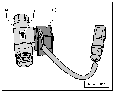
Refrigerant Cut-Off Valve
Note
- There are different versions of the shut-off valve with different functions and with different names. The following illustrated Hybrid Battery Refrigerant Shut-Off Valve 1 -N516- is for example installed on an Audi Q7 hybrid. Refer to → Heating, Ventilation and Air Conditioning; Rep. Gr.87; Refrigerant Circuit; System Overview - Refrigerant Circuit.
- There are various designations, depending on the function and the vehicle. Refer to → Heating, Ventilation and Air Conditioning; Rep. Gr.87; Refrigerant Circuit; System Overview - Refrigerant Circuit.
Shut-Off Valve with Two Switching States (Open Or Closed)
- Hybrid Battery Refrigerant Shut-Off Valve 1 -N516- (for example the Audi Q5 Hybrid)
- Heater and A/C Unit Refrigerant Shut-Off Valve -N541- (for example on Audi A3 e-tron)
- High-Voltage Battery Heater Core Refrigerant Shut-Off Valve -N542- (for example on Audi A3 e-tron)
- Refrigerant Shut-Off Valve -V424- (for example on Audi Q7 e-tron)
- If the shut-off -A- is not activated by the electronics, it is open and lets the refrigerant flow through to the evaporator in the A/C unit.
- The shut-off valve -A- is installed on vehicles with the battery cooling module. It is activated in hybrid mode when no A/C system operation is desired for the passenger compartment or for the Hybrid Battery Unit -AX1-, but is necessary for battery cooling.
- Observe the arrow -B- attached to the shut-off valve -A-, which shows the flow direction of the refrigerant (from the condenser to the evaporator in the A/C unit)
- The solenoid coil -C- attached to the shut-off valve is activated for example from the Battery Regulation Control Module -J840- → Wiring diagrams, Troubleshooting & Component locations. Use the Vehicle Diagnostic Tester in the "Guided Fault Finding" Function for the A/C System and the Battery Regulation.
- On a vehicle with two evaporators (one in the A/C unit and one for example on the Audi Q5 Hybrid) in the battery cooling module, if the measured temperature on one of the evaporators corresponds to the target value or the target value falls short, but does not reach the required target value on the other evaporator, the following adjustment is performed: the relevant control module (for example the Battery Regulation Control Module -J840- n the Audi Q5 hybrid) activates the electric A/C compressor with increased speed (thereby increasing the A/C cooling output and decreasing the pressure on the low pressure side as well as the evaporator temperature) via the A/C Compressor Control Module -J842-. If the target value falls short for the temperature of one of the evaporators, the relevant control module (for example the Battery Regulation Control Module -J840- on the Audi Q5 Hybrid the Hybrid Battery Refrigerant Shut-Off Valve 1 -N516- or the Hybrid Battery Refrigerant Shut-Off Valve 2 -N517-) activates so that the evaporator which is too cold is no longer supplied with refrigerant. Use the Vehicle Diagnostic Tester in the "Guided Fault Finding" Function for the A/C System and → Heating, Ventilation and Air Conditioning; Rep. Gr.87; System Overview - Refrigerant Circuit (for the specific vehicle).
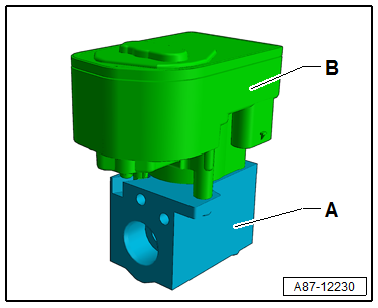
Shut-Off Valve, which is Regulated via the Characteristic Curve
- Refrigerant Shut-Off Valve 2 -N640- through Refrigerant Shut-Off Valve 5 -N643- (for example on Audi Q7 e-tron)
- Refrigerant Expansion Valve 1 -N636- (for example on Audi Q7 e-tron)
- The shut-off valve -A- is activated via a step motor -B- from the respective control module via the characteristic curve (opened or closed).
- If the shut-off valve works as a regulator valve (for example on the Audi Q7 as Refrigerant Expansion Valve 1 -N636-) it is only open until the temperature for the heat exchanger is reached. Refer to → Heating, Ventilation and Air Conditioning; Rep. Gr.87; Refrigerant Circuit; System Overview - Refrigerant Circuit.
- Shut-off valves activated via the step motor do not have a specified resting position. For this reason before performing procedures on the refrigerant circuit it must be set to a specified position (open or closed). Refer to → Heating, Ventilation and Air Conditioning; Rep. Gr.87; Refrigerant Circuit; System Overview - Refrigerant Circuit.
- Depending on the design of the refrigerant circuit multiple shut-off valves can be combined in one valve block (for example on the Audi Q7 e-tron). Refer to → Heating, Ventilation and Air Conditioning; Rep. Gr.87; Refrigerant Circuit; System Overview - Refrigerant Circuit.
- The step motor is adapted and activated via the data wires (LIN Bus) from the respective control module according to its component location. Refer to → Heating, Ventilation and Air Conditioning; Rep. Gr.87; Refrigerant Circuit; System Overview - Refrigerant Circuit. Use the Vehicle Diagnostic Tester in the "Guided Fault Finding" function.
Refrigerant Line with Inner Heat Exchanger
In this refrigerant pipe, the flowing fluid warm refrigerant on the high pressure side is delivered into the low pressure side as flowing, vapor, cold refrigerant to increase the efficiency of the A/C system.
Note
This illustration shows a refrigerant pipe with an inner heat exchanger that is installed in the Audi A4 from MY 2008 and on the Audi A5 Coupe from MY 2008. Refer to → Heating, Ventilation and Air Conditioning; Rep. Gr.87; System Overview - Refrigerant Circuit (vehicle-specific repair manual).
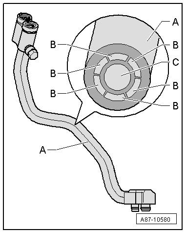
A - Refrigerant line with inner heat exchanger
B - Channel inside the refrigerant pipe through with the warm fluid refrigerant flows to the evaporator (refrigerant circuit high pressure side)
C - Channel inside the refrigerant pipe in which the vapor of cold refrigerant flow to the A/C compressor (refrigerant circuit low pressure side)
READ NEXT:
 Quick-Release Connections on Refrigerant Lines
WARNING
The quick-release coupling connectors may be
unlocked and opened only if the refrigerant circuit is
empty.
Note
This illustration shows the quick-coupling connection with
Refrigerant Circuit
Refrigerant Circuit with Expansion Valve and Evaporator
The following illustration shows only the principle of a
refrigerant circuit, the design of the refrigerant circuit in
the respective vehicle
Connections for Quick-Release Coupling on Refrigerant Circuit
General Information
Only valves and connections that are resistant to
refrigerant R134a and refrigerant oil must be installed.
Different connections (outer diameter) for high pressure and
low pre
SEE MORE:
Door B-Pillar Trim, Removing and Installing
B-Pillar Door Trim, Removing and Installing, Front
Removing
- Move the door window into the "open" position.
- Remove the window frame trim panel. Refer to
→ Body Interior; Rep. Gr.70; Front Door Trim Panels; Window
Frame Trim Panel, Removing and Installing.
- Remove
Transmission, Installing
Special tools and workshop equipment required
Clutch Module Assembly Aid -T40169-
Clutch Module Transportation Lock -T40170-
As well as all the special tools listed for the removal.
Procedure
Caution
Risk of damaging the transmission by mixing ATF and
transmission fluid (MTF) through
