Audi A4: Shock Absorber, Removing and Installing
Special tools and workshop equipment required
- Torque Wrench 1331 5-50Nm -VAG1331-
- Torque Wrench 1332 40-200Nm -VAG1332-
- Engine and Gearbox Jack -VAS6931-
- Engine/Gearbox Jack Adapter - Wheel Hub Support -T10149-
 Caution
This procedure contains mandatory replaceable parts. Refer to component overview and parts catalog prior to starting procedure.
Mandatory Replacement Parts
- Bolt - Shock Absorber Mount to Body
- Bolt/Nut - Shock Absorber to Rear Lower Transverse Link
 Note
Note
Because of different shock absorber valve systems, only install new shock absorbers from the same manufacturer on both axles, if possible.
Removing
- Before starting the procedure, determine the curb weight position. Refer to → Chapter "Wheel Bearing in Curb Weight Position, Lifting Vehicles with Coil Spring".
- Remove the rear wheel. Refer to → Chapter "Wheels and Tires".
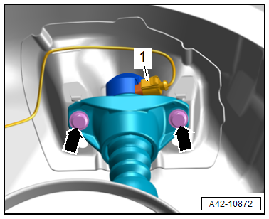
- Remove the expanding rivets -2-.
- Pull the wind deflector -1- slightly outward -arrow- and remove.
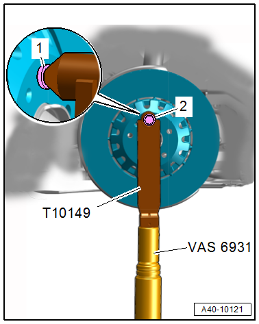
- Turn the wheel hub, until a wheel bolt hole is at the top.
- Install the -T10149- with a wheel bolt -2- on the wheel hub.
Note
Ignore item -1-.
- Insert the -T10149- in the -VAS6931- and lift the wheel bearing housing slightly.
 WARNING
Risk of accident!
- Do not lower the wheel bearing housing with the -VAS6931- if the upper or lower threaded connection for the shock absorber was separated.
- Do not leave the -VAS6931- under the vehicle any longer than necessary.
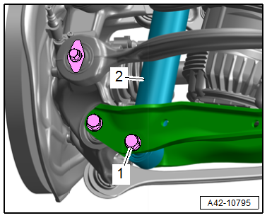
- Equipped on some models: disconnect the connector -1-.
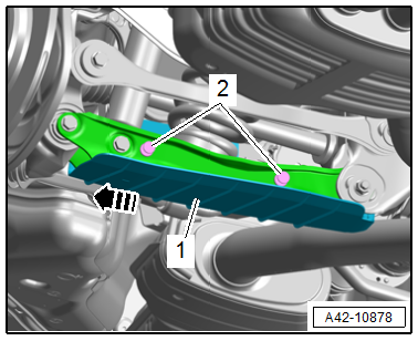
- Remove the bolts -arrows- on the upper shock absorber fastener.
- Disconnect the connector -1- and remove the shock absorber -2-.
Installing
Install in reverse order of removal and note the following:
- Install the threaded connections up to the stop but do not tighten yet.
Note
Bonded rubber bushings have a limited range of rotation. Only tighten the threaded connections for the suspension when the vehicle is in curb weight position.
- Lift the wheel bearing in curb weight position. Refer to → Chapter "Wheel Bearing in Curb Weight Position, Lifting Vehicles with Coil Spring".
- Overview table for when an axle alignment is needed. Refer to → Chapter "Need for Axle Alignment, Evaluating".
Tightening Specifications
- Refer to → Chapter "Overview - Wheel Bearing"
- Refer to → Chapter "Wheels and Tires"
READ NEXT:
 Spring, Removing and Installing
Special tools and workshop equipment required
Pneumatic/Hydraulic Foot Pump -VAS6179-
Spring Tensioning System -VAS6274-
Spring Tensioning System - Spindle -VAS6274/3-
Spring Tensioning System -
Overview - Wheel Bearing
Overview - Wheel Bearing, FWD
1 - Wheel Bearing Unit
Removing and installing. Refer to
→ Chapter "Wheel Bearing Unit, Removing and Installing, FWD".
Handling the wheel bearing. R
SEE MORE:
Glass Panel, Removing and Installing
Glass Panel, Removing and Installing, Sedan
Caution
This procedure contains mandatory replaceable parts.
Refer to component overview and parts catalog prior to
starting procedure.
Mandatory Replacement Parts
Screw - Glass Panel
The following components must be replaced after removal. R
Stabilizer Bar, Removing and Installing
Special tools and workshop equipment required
Torque Wrench 1331 5-50Nm -VAG1331-
Caution
This procedure contains mandatory replaceable parts.
Refer to component overview and parts catalog prior to
starting procedure.
Mandatory Replacement Parts
Nut - Stabilizer Bar to Coupling Rod
