Audi A4: Spring, Removing and Installing
Special tools and workshop equipment required
- Pneumatic/Hydraulic Foot Pump -VAS6179-
- Spring Tensioning System -VAS6274-
- Spring Tensioning System - Spindle -VAS6274/3-
- Spring Tensioning System - T-Bar -VAS6274/5-
- Supplement Set - Thrust Plate with Securing Plate -VAS6274/12-2-
- Supplement Set - Support Plate for Spreader -VAS6274/12-5-
- Spring Tensioning System - Socket -VAS6274/6-
- Supplement Set - Thrust Plate with Swivel Bearing -VAS6274/12-1-
- Supplement Set - Thrust Plate with Securing Plate -VAS6274/12-2-
- Supplement Set - Spring Support -VAS6274/12-3-
- Supplement Set - 89mm Plunger -VAS6274/12-7-
- Spring Tensioning System - T-Bar -VAS6274/5-
- Spring Tensioning System - Spreader Device -VAS6274/8-
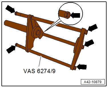
- Spring Tensioning System - Hydraulic Tensioner -VAS6274/9-
- Spring Tensioning System - Audi Set -VAS6274/10-
- Supplement Set -VAS6274/12-
Removing
- Remove the rear wheel. Refer to → Chapter "Wheels and Tires".
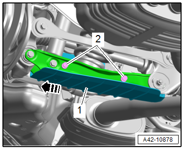
- Remove the expanding rivets -2-.
- Pull the wind deflector -1- slightly outward -arrow- and remove.
AWD Vehicles, Right Side of the Vehicle
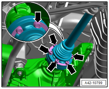
- Remove the bolts (arrows) on the inner CV joint and press the inside of the drive axle upward.
AWD Vehicles, Left Side of the Vehicle
- Remove the heat shield.
- Remove the bolts on the inner CV joint and press the inside of the drive axle upward.
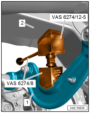
- Place the spreader device, consisting of -VAS6274/8- and -VAS6274/12-5-, between the front upper transverse link -1- and the longitudinal member -2- as shown, and pretension slightly.
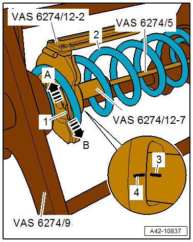
- Press the locking plate -2- outward in the direction of the -arrow A- (open).
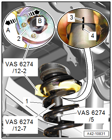
- Insert the -VAS6274/12-2- as shown from the outside into the coil spring -1-.
- Insert the -VAS6274/12-7- with the -VAS6274/5- into the thrust plate and turn 90º until the line marking -3- on the thrust plate is flush with the line marking -4- on the plunger.
- Pull the plunger downward into the thrust plate and secure with the locking in the direction of the plate -arrow B- (close).
- Remove the -VAS6274/5-.
 Caution
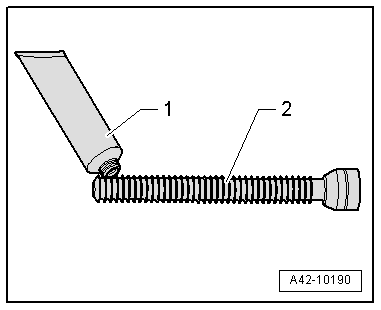
There is a risk of damaging the spindle due to missing or incorrect grease.
Coat the front area of the -VAS6274/3--2- lightly with the accompanying grease -1- before removal and installation of each spring.
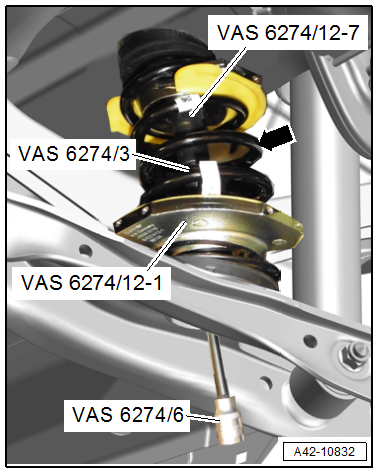
- Insert the -VAS6274/12-1- as shown from the outside into the coil spring -arrow-.
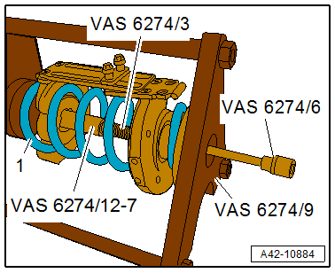
- Lightly lubricate the -VAS6274/3- in the front area and screw loosely into the -VAS6274/12-7- using the -VAS6274/6-.
 WARNING
Risk of accident!
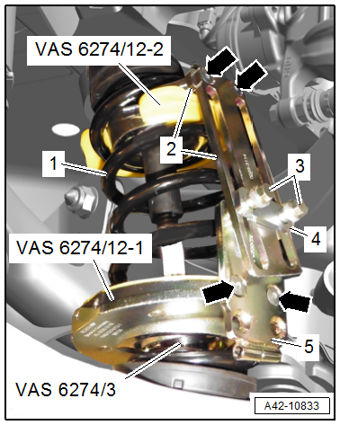
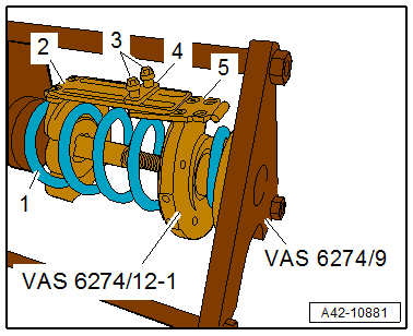
The coil spring may only be tensioned or released if the locking device brackets -2 and 5- are connected to each other through both bolts -3-.
- Turn the -VAS6274/12-2- all the way upward and turn the -VAS6274/12-1- all the way downward.
- Tighten the locking device brackets -2 and 5- to both thrust plates -arrows-.
- The locking device brackets face forward.
 Note
Note
Depending on the type of suspension, the attachment point of the locking device brackets to the thrust plates can be different.
- Screw in the locking device bracket bolts -3- for both thrust plates to the backing plate -4- by hand.
- Lightly tension the thrust plates using the -VAS6274/3-.
- Check if the coil spring -1- is seated correctly in the thrust plates.
Caution
There is a risk of damaging the threads.
- The -VAS6274/3- must not be tensioned or released using an impact wrench.
- Always turn the spindle using a commercially available ratchet.
There is a risk of damaging the transverse link.
The tensioner thrust plates must not contact the transverse link when tensioning the coil springs. Turn the thrust plates if necessary.
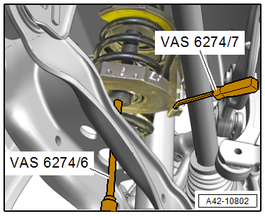
- Tension the coil spring with the -VAS6274/6- by counterholding with the -VAS6274/7-.
WARNING
Risk of injury due to uneven tensioning of the coil springs.
The coil spring tension may only be released in the -VAS6274/9-.
- Tension the coil spring until it can be removed.
- If necessary for subsequent work, remove the -VAS6274/8- with -VAS6274/12-5-.
Release the coil spring tension in the -VAS6274/9-.
WARNING
Loose threaded connections increase the risk of injury.
Make sure the nuts -arrows- are secure and tighten if necessary before using the - VAS6274/9-.
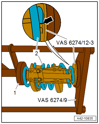
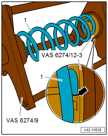
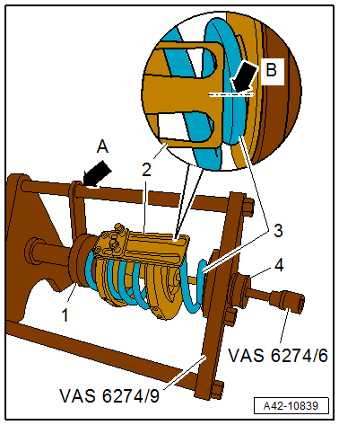
- Mount the -VAS6274/12-3- on the -VAS6274/9-.
- Place the pretensioned coil spring -2- with the bottom side on the spring support.
- The end of the spring coil must rest on the spring support stop -arrow-.
- Guide the hydraulic tensioner plunger -1- out all the way to the coil spring and do not tighten.
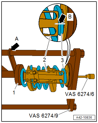
- Mark the plunger position -1- on the -VAS6274/9--arrow A- with a waterproof felt-tip pen, for example.
- Mark the position of the anti-twist mechanism -2- on the coil spring -3--arrow B- with a waterproof felt-tip pen, for example.
Note
The marks are needed when tightening for installation.
Caution
There is a risk of damaging the threads.
- The -VAS6274/3- must not be tensioned or released using an impact wrench.
- Always turn the spindle using a commercially available ratchet.
- Release the coil spring tension completely using the -VAS6274/6- with the hydraulic tensioner.
- After the coil spring -1- tension is released, remove the -VAS6274/3-.
- Remove the locking device bolts -2- and remove with the backing plate -3-.
- Remove the -VAS6274/12-1-.
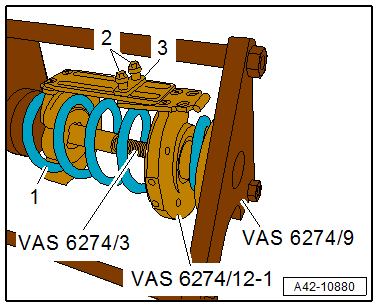
- Press the locking plate -1- outward in the direction of the -arrow B- (open).
- Remove the -VAS6274/12-7- with the -VAS6274/5- from the -VAS6274/12-2-.
- Remove the thrust plate from the coil spring -2-.
Note
- Ignore items -3, 4 and arrow A-.
- If the opposite coil spring in the vehicle should also be removed, then the installation position and attachment point of the locking device bracket to the thrust plates must be marked for later installation.
- If the coil spring is replaced, then the applied mark must be transferred to the new coil spring.
Installing
Install in reverse order of removal and note the following:
- Insert the coil spring -1- into the -VAS6274/9-.
- The end of the spring coil on the bottom of the coil spring must rest against -arrow- the -VAS6274/12-3-
- Insert the -VAS6274/12-2- as shown into the coil spring -2-.
- Press the locking plate -1- outward in the direction of the -arrow B- (open).
- Insert the -VAS6274/12-7- with the -VAS6274/5- into the thrust plate and turn 90º until the line marking -4- on the thrust plate is flush with the line marking -3- on the plunger.
- Pull the plunger into the thrust plate and secure with the locking plate in the direction of the -arrow A- (close).
- Remove the -VAS6274/5-.
- Insert the -VAS6274/12-1- into the coil spring -1-.
- When removing, note the marks applied for the installation position and the locking device bracket positions -2 and 5- to the thrust plates for the corresponding side of the vehicle.
- Tighten the locking device bolts -3- to the backing plate -4- by hand.
- Insert the -VAS6274/3- loosely into the -VAS6274/12-7- using the -VAS6274/6-. Tension the coil spring -1- slightly using the -VAS6274/9- while doing so.
- Insert the 130 mm long centering sleeve -4- all the way.
- Align the locking device -2- to the mark applied during removal -arrow B- on the coil spring -3-.
- Tension the coil spring using the -VAS6274/6- and at the same time using the -VAS6274/9- up to the previously applied mark -arrow A-.
- Make sure when tensioning that the centering sleeve does not slide off of the spindle. Push back if necessary.
Note
If necessary, the thrust plates must be held in position up to the mark -arrow B- using the -VAS6274/7-.
Caution
There is a risk of damaging the threads.
- The Spring Tensioning System - Spindle -VAS6274/3- must not be tensioned or released using an impact wrench.
- Always turn the spindle using a commercially available ratchet.
- Continue to tension the coil spring using the -VAS6274/6- until the coil spring rests loosely on the hydraulic tensioner.
- Release the tension on the hydraulic tensioner, and remove the centering sleeve and the pretensioned coil spring.
- -VAS6274/8- fixed with - VAS6274/12-5-.
- Bring the coil spring and the spring plate into the installation position. Refer to → Fig. "Coil Spring and Spring Plate Installation Position".
Caution
There is a risk of damaging the threads.
- The -VAS6274/3- must not be tensioned or released using an impact wrench.
- Always turn the spindle using a commercially available ratchet.
- Release the tension on the coil spring with the -VAS6274/6-. Do so by counterholding with the -VAS6274/7-.
Caution
There is a risk of damaging the transverse link.
- The tensioner thrust plates must not contact the transverse link when releasing the tension on the coil springs. Turn the thrust plates if necessary.
- Overview table for when an axle alignment is needed. Refer to → Chapter "Need for Axle Alignment, Evaluating".
Tightening Specifications
- Refer to → Chapter "Overview - Drive Axle"
- Refer to → Fig. "Heat Shield - Tightening Specification"
READ NEXT:
 Overview - Wheel Bearing
Overview - Wheel Bearing, FWD
1 - Wheel Bearing Unit
Removing and installing. Refer to
→ Chapter "Wheel Bearing Unit, Removing and Installing, FWD".
Handling the wheel bearing. R
Wheel Bearing Housing, Removing and Installing
Special tools and workshop equipment required
Torque Wrench 1332 40-200Nm -VAG1332-
Engine and Gearbox Jack -VAS6931-
Engine/Gearbox Jack Adapter - Wheel Hub Support -T10149-
Caution
Thi
SEE MORE:
General Safety Precautions
As per VBG 20, German industrial liability insurance
association.
Pay attention to the workshop-specific instructions. It
should be kept in the workshop.
Product Characteristics
Refrigerants used in motor vehicle air conditioning systems
belong to the new generation of refrigerants based on
Instrument cluster overview
Fig. 2 Instrument cluster overview (Audi virtual cockpit)
Fig. 3 Instrument cluster overview (analog)
Depending on the vehicle equipment, the following items may appear in the
instrument cluster:
Left dial
Tachometer
Tab area
Central area
Status line (one or two lines)
Right dial
Co
