Audi A4: Quick-Release Connections on Refrigerant Lines
 WARNING
The quick-release coupling connectors may be unlocked and opened only if the refrigerant circuit is empty.
 Note
Note
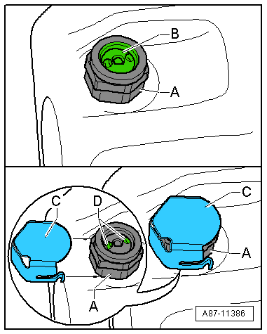
- This illustration shows the quick-coupling connection with a refrigerant pipe with an inner heat exchanger that is installed in the Audi A4 from MY 2008 and on the Audi A5 Coupe from MY 2008. Refer to → Heating, Ventilation and Air Conditioning; Rep. Gr.87; System Overview - Refrigerant Circuit (vehicle-specific repair manual).
- The retaining ring -A- must be opened using, for example, the Air Conditioner Couplings Release Tool -T40149- in order to remove the refrigerant line -D-. Refer to → Heating, Ventilation and Air Conditioning; Rep. Gr.87; System Overview - Refrigerant Circuit (vehicle-specific repair manual).
- The quick-release coupling connectors -B- and -G- are to be replaced after removing the refrigerant line with the respective support ring -E- or -H- and O-ring -F- or -J-. Refer to → Heating, Ventilation and Air Conditioning; Rep. Gr.87; System Overview - Refrigerant Circuit (vehicle-specific repair manual) and the Parts Catalog).
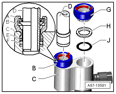
A - Retaining ring (inside the quick-release coupling connector, high pressure side)
B - Quick-release coupling connector with retaining ring "high pressure side"
C - Refrigerant line with an inner heat exchanger
D - Refrigerant line "high pressure side"
E - Support ring "high pressure side"
F - O-ring "high pressure side"
G - Quick-release coupling connector with retaining ring "low pressure side"
H - Support ring "low pressure side"
J - O-ring "low pressure side"
Note
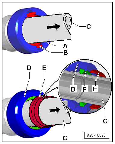
- There are different quick-release coupling versions -A- and -D-. The refrigerant lines -C-, for example, can unlocked and removed using the Air Conditioner Couplings Release Tool -T40149/1- in the same manner for both versions of the quick-release couplings.
- The check pins on the -B- quick-release couplings -A- installed at SOP are visible -C-, when the locked refrigerant line -C- is pulled in the direction of arrow.
- Beginning with MY 2010, as a running change, the quick-release coupling -D- and the refrigerant line -C- are being installed in the same manner as the quick-release coupling -A-. If the refrigerant line -C- is pulled in the direction of arrow after assembling, the ring -E- will come out of the quick-release coupling -D- installed and will show that the retaining ring -F- is completely latched to the refrigerant line -C-. Then the ring -E- can be removed from the refrigerant line -C-.
O-Ring Seals
These rings seal off the connection points between individual components of the refrigerant circuit.
Only O-rings that are resistant to refrigerant R134a and refrigerant oil must be installed. Make sure they are original replacement parts.
O-ring seals:
- Always use only once.
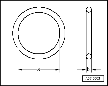
- Make sure diameters -a- and -b- are correct.
- Coat with refrigerant oil before installing. Refer to → Heating, Ventilation and Air Conditioning; Rep. Gr.87; System Overview - Refrigerant Circuit (vehicle-specific repair manual) and the Parts Catalog.
Note
The color coding of refrigerant circuit O-rings with R134a has been discontinued. Black and colored O-rings are used. Refer to the Parts Catalog and → Heating, Ventilation and Air Conditioning; Rep. Gr.87; System Overview - Refrigerant Circuit (vehicle-specific repair manual).
Refrigerant Circuit Pipes and Hoses
The mixture of refrigerant oil and refrigerant R134a corrodes certain metals (such as copper) and alloys and dissolves some hose materials. Therefore use original replacement parts only.
Pipes and hoses are joined by threaded connections or special plug connectors.
Note
Observe specified torque for threaded connections, use appropriate release tools for plug connectors.
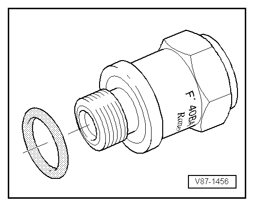
Pressure Relief Valve
The pressure relief valve is installed on the A/C compressor or receiver/dryer.
At a pressure of approximately 38 bar (551 psi) positive pressure, valve opens and closes again once pressure has dissipated (approximately 30 bar (435 psi) ).
Refrigerant does not escape completely.
Note
- Depending on the version, a transparent plastic disc -B- may be installed on the pressure relief valve -A-, which breaks off as soon as the valve is activated.
- Depending on the pressure relief valve version -A-, an additional cover -C- can be slid onto the pressure relief valve -A-. If the pressure in the refrigerant circuit does rise above the pressure relief valve -A- opening pressure and the valve opens, the refrigerant does not escape in one direction, but rather it is distributed through the openings -D- under the cover -C-.
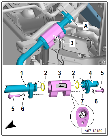
Check Valves
The check valves disconnect in different areas of the refrigerant circuit.
Note
- The illustrated check valve -3- if for example installed on an Audi Q7 e-tron
- The check valves in the refrigerant circuit in the flow direction have a specified residual pressure, approximately 0.1 bar or 100 mbar (1.5 psi). So that the refrigerant circuit can be completely evacuates (residual pressure less than 5 mbar (0.10 psi) ) all electrically activated valves must be opened.
- Depending on the version the flow direction can be marked using a sticker.
READ NEXT:
 Refrigerant Circuit
Refrigerant Circuit with Expansion Valve and Evaporator
The following illustration shows only the principle of a
refrigerant circuit, the design of the refrigerant circuit in
the respective vehicle
Connections for Quick-Release Coupling on Refrigerant Circuit
General Information
Only valves and connections that are resistant to
refrigerant R134a and refrigerant oil must be installed.
Different connections (outer diameter) for high pressure and
low pre
SEE MORE:
Trailer Hitch
Trailer Hitch Socket, Removing and Installing - Version 1
Removing
- Turn off the ignition and remove the key.
- Remove the bolts -arrows-.
- Detach the socket from the retaining plate.
Socket with Rear Fog Lamp Shut-Off Contact Switch -F216-:
- Remove harness connector -2-
for
Fuel Filler Door Unit
Overview - Fuel Filler Door Unit
1 -
Drain Hose
From the fuel filler door unit
Removing and installing. Refer to
→ Chapter "Fuel Filler Door Unit Drain Hose, Removing and Installing".
2 -
Emergency Release Cable
Removing and installing. Refer to
→ Chapter "E
