Audi A4: Pedestrian Protection
Overview - Pedestrian Protection
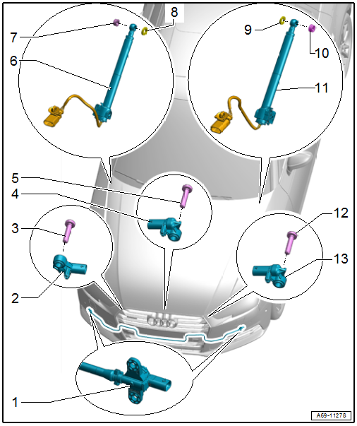
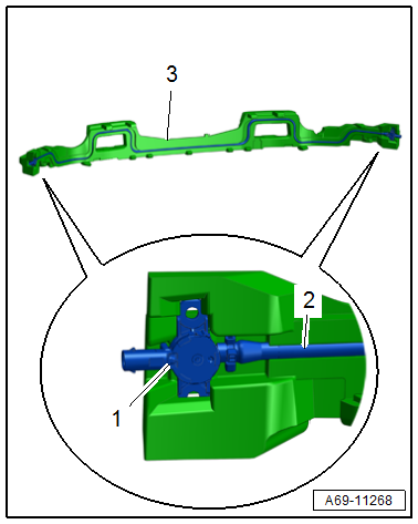
1 - Driver Side Pedestrian Protection Crash Sensor 2 -G851-/Front Passenger Side Pedestrian Protection Crash Sensor 2 -G852-
- Unit with pressure hose
- Component location: In the molded foam part on the impact member
- Must be replaced when
- The molded foam part is visibly damaged.
- The impact member is visibly deformed.
- The bumper cover is deformed.
- The pressure hose is damaged.
- Place the pressure hose in the groove on the molded foam part.
- Insert the pressure hose in the center of the molded foam part, the projecting end is the same on both the left and right side.
- Do not kink or squeeze the pressure hose.
- Removing and installing. Refer to → Chapter "Pedestrian Protection Crash Sensor, Removing and Installing".
2 - Front Passenger Side Pedestrian Protection Crash Sensor -G571-
- Equipped on some models
- Component location: On the bumper cover bracket
- Removing and installing. Refer to → Chapter "Pedestrian Protection Center Crash Sensor -G693-, Removing and Installing".
3 - Bolt
- 8 Nm
4 - Pedestrian Protection Center Crash Sensor -G693-
- Component location: On the bumper cover bracket
- Removing and installing. Refer to → Chapter "Pedestrian Protection Center Crash Sensor -G693-, Removing and Installing".
5 - Bolt
- 8 Nm
6 - Pedestrian Protection Trigger 1 -G598-
- Removing and installing. Refer to → Chapter "Pedestrian Protection Trigger 1 -G598-/ Pedestrian Protection Trigger 2 -G599-, Removing and Installing".
7 - Clip
8 - Seal
9 - Seal
10 - Clip
11 - Pedestrian Protection Trigger 2 -G599-
- Removing and installing. Refer to → Chapter "Pedestrian Protection Trigger 1 -G598-/ Pedestrian Protection Trigger 2 -G599-, Removing and Installing".
12 - Bolt
- 8 Nm
13 - Driver Side Pedestrian Protection Crash Sensor -G570-
- Equipped on some models
- Component location: On the bumper cover bracket
- Removing and installing. Refer to → Chapter "Pedestrian Protection Center Crash Sensor -G693-, Removing and Installing".
Pedestrian Protection Center Crash Sensor -G693-, Removing and Installing
 Note
Note
The Driver Side Pedestrian Protection Crash Sensor -G570-/Front Passenger Side Pedestrian Protection Crash Sensor -G571- is removed and installed in the same way.
Removing
- Remove the lock carrier cover. Refer to → Body Exterior; Rep. Gr.63; Front Bumper; Attachments, Removing and Installing.
- Remove the bolt -1-, and remove the Pedestrian Protection Center Crash Sensor -G693--2- from the bumper.
 WARNING
Risk of injury due to involuntary deployment.
Before handling pyrotechnic components (For example, disconnecting the connector), the person handling it must "discharge static electricity". For example, this can be done by briefly touching the door striker.
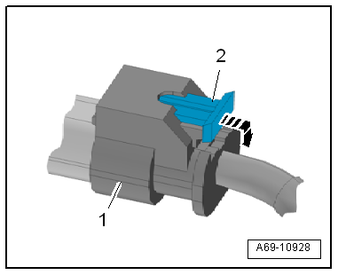
- Disconnect the connector -3-.
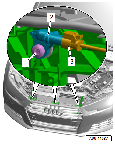
- To do this pull out the connector lock -2-, push down in the direction of -arrow-, and disconnect the connector -1- on the crash sensor.
Installing
WARNING
Risk of injury due to involuntary deployment.
- Pay attention to the safety precautions when working with pyrotechnic components. Refer to → Chapter "Safety Precautions when Working with Pyrotechnic Components".
- Before handling pyrotechnic components (For example, connecting a connector), the person handling it must "discharge static electricity". For example, this can be done by briefly touching the door striker.
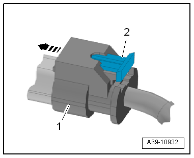
- Attach the connector -1- to the crash sensor until it clicks into place in the direction of -arrow-.
- Push in the connector lock -2- to secure the connector.
Further installation is performed in reverse order of removal, while noting the following:
Note
- Make sure the connectors are pushed in all the way and that they engage audibly.
- Make sure the wires are not pinched.
WARNING
Repairing pyrotechnic components (For example the airbag and seat belt tensioner) incorrectly increases the risk of injuries due to unintentional deployments when the battery is connected.
- The ignition must be on when connecting the battery.
- Make sure that no one is inside the vehicle at the time when the battery is connected.
- Connect the battery ground cable with the ignition switched on. Refer to → Electrical Equipment; Rep. Gr.27; Battery; Battery, Disconnecting and Connecting.
Note
If the Airbag Indicator Lamp -K75- indicates a fault, check the DTC memory, erase it and check it again using the Vehicle Diagnostic Tester.
Installation instructions: For example tightening specifications, replacing components. Refer to → Chapter "Overview - Pedestrian Protection".
Pedestrian Protection Crash Sensor, Removing and Installing
Removing
WARNING
Risk of injury due to involuntary deployment.
Pay attention to the safety precautions when working with pyrotechnic components. Refer to → Chapter "Safety Precautions when Working with Pyrotechnic Components".
- Disconnect the battery ground cable with the ignition turned on. Refer to → Electrical Equipment; Rep. Gr.27; Battery; Battery, Disconnecting and Connecting.
- Remove the bumper cover. Refer to → Body Exterior; Rep. Gr.63; Front Bumper; Bumper Cover, Removing and Installing.
WARNING
Risk of injury due to involuntary deployment.
Before handling pyrotechnic components (For example, disconnecting the connector), the person handling it must "discharge static electricity". For example, this can be done by briefly touching the door striker.
- Disconnect the connector -1- from the crash sensor by pulling out the connector lock -2- and pressing it down in the direction of -arrow-.
- Repeat the procedure on the opposite side.
- Remove the molded foam part. Refer to → Body Exterior; Rep. Gr.63; Front Bumper; Attachments, Removing and Installing.
- Disengage the pedestrian protection crash sensor -1- from the molded foam part -3- and remove it with the pressure hose -2-.
Installing
WARNING
Risk of injury due to involuntary deployment.
- Pay attention to the safety precautions when working with pyrotechnic components. Refer to → Chapter "Safety Precautions when Working with Pyrotechnic Components".
- Before handling pyrotechnic components (For example, connecting a connector), the person handling it must "discharge static electricity". For example, this can be done by briefly touching the door striker.
- Engage the pedestrian protection crash sensor into the molded foam part.
WARNING
Risk of malfunction.
Do not kink or stretch the pressure hose.
- The pressure hose must be inserted without any tension.
- Install the molded foam part with the pedestrian protection crash sensor. Refer to → Body Exterior; Rep. Gr.63; Front Bumper; Attachments, Removing and Installing.
- Attach the connector -1- to the crash sensor until it clicks into place in the direction of -arrow-.
- Push in the connector lock -2- to secure the connector.
Further installation is performed in reverse order of removal, while noting the following:
Note
- Make sure the connectors are pushed in all the way and that they engage audibly.
- Make sure the wires are not pinched.
WARNING
Repairing pyrotechnic components (For example the airbag and seat belt tensioner) incorrectly increases the risk of injuries due to unintentional deployments when the battery is connected.
- The ignition must be on when connecting the battery.
- Make sure that no one is inside the vehicle at the time when the battery is connected.
- Connect the battery ground cable with the ignition switched on. Refer to → Electrical Equipment; Rep. Gr.27; Battery; Battery, Disconnecting and Connecting.
Note
If the Airbag Indicator Lamp -K75- indicates a fault, check the DTC memory, erase it and check it again using the Vehicle Diagnostic Tester.
Installation instructions: For example tightening specifications, replacing components. Refer to → Chapter "Overview - Pedestrian Protection".
Pedestrian Protection Trigger 1 -G598-/ Pedestrian Protection Trigger 2 -G599-, Removing and Installing
Removing
WARNING
Risk of injury due to involuntary deployment.
Pay attention to the safety precautions when working with pyrotechnic components. Refer to → Chapter "Safety Precautions when Working with Pyrotechnic Components".
- Disconnect the battery ground cable with the ignition turned on. Refer to → Electrical Equipment; Rep. Gr.27; Battery; Battery, Disconnecting and Connecting.
- Remove the fender cover. Refer to → Body Exterior; Rep. Gr.50; Fender; Overview - Fender.
WARNING
Risk of injury due to involuntary deployment.
Before handling pyrotechnic components (For example, disconnecting the connector), the person handling it must "discharge static electricity". For example, this can be done by briefly touching the door striker.
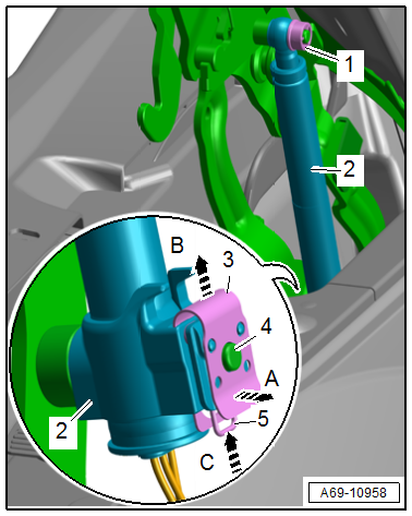
- Press the release to free up and disconnect the pedestrian protection trigger connector.
- Remove the clip -1- with a screwdriver.
- Release the clip -3- to do so pull on the clip in the direction of -arrow A- and at the same time push in the direction of -arrow B- over the pin -4-.
- Press the securing clip -5- in the direction of -arrow C- and hold it pressed and at the same time remove the trigger for the pedestrian protection -2- from the pin.
Installing
WARNING
Risk of injury due to involuntary deployment.
- Pay attention to the safety precautions when working with pyrotechnic components. Refer to → Chapter "Safety Precautions when Working with Pyrotechnic Components".
- Before handling pyrotechnic components (For example, connecting a connector), the person handling it must "discharge static electricity". For example, this can be done by briefly touching the door striker.
Further installation is the reverse order of removal.
Note
- Make sure the connectors are pushed in all the way and that they engage audibly.
- Make sure the wires are not pinched.
WARNING
Repairing pyrotechnic components (For example the airbag and seat belt tensioner) incorrectly increases the risk of injuries due to unintentional deployments when the battery is connected.
- The ignition must be on when connecting the battery.
- Make sure that no one is inside the vehicle at the time when the battery is connected.
- Connect the battery ground cable with the ignition switched on. Refer to → Electrical Equipment; Rep. Gr.27; Battery; Battery, Disconnecting and Connecting.
Note
If the Airbag Indicator Lamp -K75- indicates a fault, check the DTC memory, erase it and check it again using the Vehicle Diagnostic Tester.
Installation instructions: For example tightening specifications, replacing components. Refer to → Chapter "Overview - Pedestrian Protection".
Special Tools
Special tools and workshop equipment required
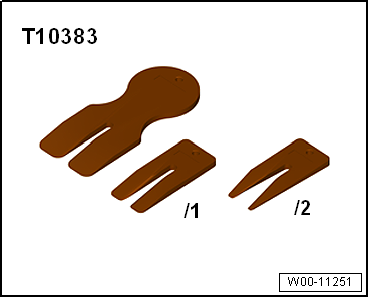
- Wedge Set -T10383-
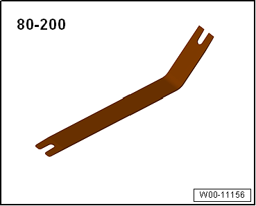
- Pry Lever -80-200-
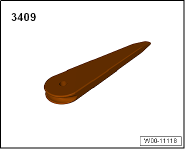
- Trim Removal Wedge -3409-
- Not illustrated:
- Clip Pliers -VAS211001-
READ NEXT:
 Front Door Trim Panels
Overview - Front Door Trim Panel
1 - Pull Handle with Armrest
Removing and installing. Refer to
→ Chapter "Front Pull Handle, Removing and Installing".
2 - Switch Mount
Front Door Trim Panel, Removing and Installing
Special tools and workshop equipment required
Wedge Set -T10383-
Wedge Set - Wedge 1 -T10383/1-
Removing
- Switch off the ignition.
- Unclip the decorative trim -1-
using the -T10383/1-
SEE MORE:
Efficiency assist
Description
Applies to: vehicles with efficiency assist
Efficiency assist can assist the driver with predictive
information in order to reduce fuel consumption.
Depending on vehicle equipment, the system
may access data from the navigation system,
the camera behind the windshield, and the radar
s
When driving
Starting to drive, stopping, and parking
Starting from a stop
Press and hold the brake pedal.
Start the engine.
Select "D" or "R".
Release the parking brake.
Release the brake pedal. The vehicle may roll.
Press the accelerator pedal to accelerate.
Securing the vehicle against rolling
Secure
