Audi A4: Tie Rod, Removing and Installing
Special tools and workshop equipment required
- Torque Wrench 1332 40-200Nm -VAG1332-
- Torque Wrench Insert - Open Jaw -VAG1923-
 Caution
This procedure contains mandatory replaceable parts. Refer to component overview and parts catalog prior to starting procedure.
Mandatory Replacement Parts
- Spring Clamp - Boot to Tie Rod End
- Clamp - Boot to Steering Gear
Removing
 Note
Note
Follow the guidelines for clean working conditions. Refer to → Chapter "Guidelines for Clean Working Conditions".
- Remove the boot. Refer to → Chapter "Boot, Removing and Installing".
- Position the front wheels as follows:
- For the left tie rod, turn the steering to the left until it stops
- For the right tie rod, turn the steering to the right until it stops
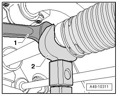
- Remove the spring clip with the -VAG1923--2- by counterholding at the steering gear steering rack with an open end wrench -1-.
Caution
There is a risk of the steering gear being destroyed by moisture and dirt.
There must be a visible film of grease present on the steering rack near the splines. If the film of grease is missing, replace the steering gear.
Installing
Install in reverse order of removal and note the following:
- Install the boot. Refer to → Chapter "Boot, Removing and Installing".
- Overview table for when an axle alignment is needed. Refer to → Chapter "Need for Axle Alignment, Evaluating".
Tightening Specifications
- Refer to → Chapter "Overview - Steering Gear"
- Refer to → Chapter "Overview - Steering Gear, Tie Rods"
- Refer to → Chapter "Wheels and Tires"
Tie Rod End, Removing and Installing
Special tools and workshop equipment required
- Torque Wrench 1332 40-200Nm -VAG1332-
- Torque Wrench 1332 Insert - Ring Wrench - 21mm -VAG1332/7-
- Engine and Gearbox Jack -VAS6931-
- Ball Joint Splitter -VAS251805-
Caution
This procedure contains mandatory replaceable parts. Refer to component overview and parts catalog prior to starting procedure.
Mandatory Replacement Parts
- Spring Clamp - Boot to Tie Rod End
Removing
- Remove the front wheel. Refer to → Chapter "Wheels and Tires".
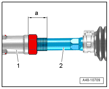
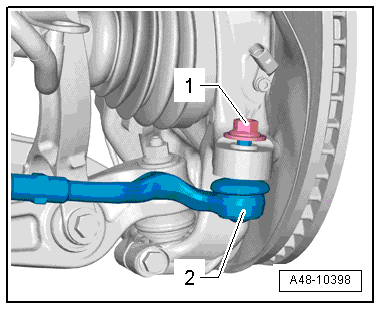
- Measure the dimension -a- between the tie rod head -1- and the left and right tie rod -2- and make a note of the value.
- Dimension -a- should be the same on the left and right sides after installing.
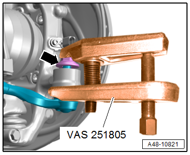
- To protect the threads, remove the nut -arrow- from the tie rod end joint pin until it is flush with the joint pin threads.
 WARNING
There is a risk of injury from falling components.
When pressing off, the tie rod end loosens abruptly from the wheel bearing housing. Use, for example, the -VAS6931- to secure.
Caution
There is a risk of damaging the ball joint puller.
Make sure that both puller lever arms are parallel to each other when using maximum force.
- Remove the tie rod end with the -VAS251805- from the wheel bearing housing.
- Remove the nut. Counterhold on the joint pin with a 6 mm inner hex socket if necessary.
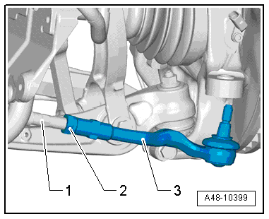
- Only loosen the nut -2- while counterholding the tie rod end -3-.
- Remove the tie rod end, while counterholding at the tie rod hex fitting -1- if necessary.
Installing
Install in reverse order of removal and note the following:
- Screw the tie rod end -1- on the tie rod -2- until dimension -a-, which was measured during removal, is reached.
- Align the tie rod end so that the pin is in the installation position.
- Insert the tie rod end all the way into the wheel bearing housing.
- Counterhold at the joint pin with a 6 mm hex socket wrench if necessary to tighten the nut -1-
- Tighten the nut -2-
- Overview table for when an axle alignment is needed. Refer to → Chapter "Need for Axle Alignment, Evaluating".
Tightening Specifications
- Refer to → Chapter "Overview - Steering Gear"
- Refer to → Chapter "Wheels and Tires"
READ NEXT:
 Steering Gear End Positions, Adapting
Special tools and workshop equipment required
Vehicle Diagnostic Tester
Note
If the connection between the steering gear and the steering
wheel is disconnected, the end position of the ste
SEE MORE:
Lower Transverse Link, Removing and Installing
Rear Lower Transverse Link, Removing and Installing
Special tools and workshop equipment required
Torque Wrench 1332 40-200Nm -VAG1332-
Engine and Gearbox Jack -VAS6931-
Engine/Gearbox Jack Adapter - Wheel Hub Support -T10149-
Caution
This procedure contains mandatory replaceable parts
Safety belts
General information
Each seat is equipped with a three-point safety
belt. Safety belts that are worn correctly are the
most effective way to reduce the risk of serious or
fatal injuries in a collision. Therefore, wear your
safety belt correctly and make sure that all vehicle
passengers are also wear
