Audi A4: Reservoir
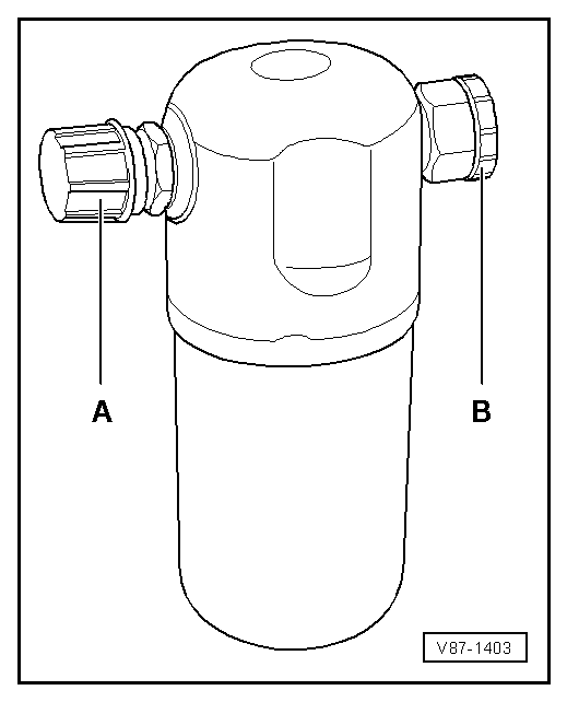
The reservoir collects the vaporized and gaseous mixture coming from the evaporator to ensure the compressor only receives gaseous refrigerant. Gaseous refrigerant is formed from the vapor.
The refrigerant oil flowing in the circuit is not retained in the reservoir as it has an oil drilling.
Moisture which has entered the refrigerant circuit during repairs will be collected by a filter (desiccant bag) in the reservoir.
Gaseous refrigerant is extracted with oil by the A/C compressor.
 Note
Note
- Replace the reservoir if refrigerant circuit has been open for a long time (beyond the normal repair time) and moisture has penetrated inside, or if required due to a specific complaint. Refer to → Chapter "Refrigerant Circuit Components, Replacing".
- Remove the sealing plugs -A- and -B- only immediately before installing.
- A desiccant bag in an unsealed reservoir is saturated with moisture after a short period of time and unusable.
- When installing, note arrow for direction of flow if necessary.
Restrictor
Restrictor in Front of the Evaporator
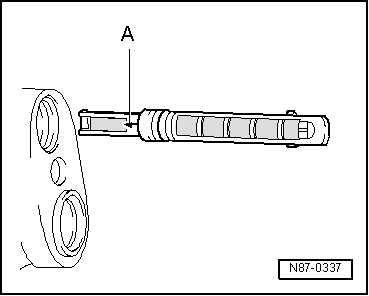
The restrictor creates a constriction. This restriction reduces the flow and creates high and low pressure sides in the refrigerant circuit. Before the restrictor the refrigerant which is under a higher pressure is warm. After the restrictor the refrigerant which is under a low pressure is cold. Before the restriction there is a strainer for contaminants and after the restriction there is a strainer, to atomize the refrigerant before it reaches the evaporator.
Note
- Arrow -A- on restrictor points to the evaporator.
- Replace after each opening of the circuit.
- There are different versions, therefore pay attention to the different customer service information sources. Refer to → Heating, Ventilation and Air Conditioning; Rep. Gr.87; System Overview - Refrigerant Circuit and (vehicle-specific repair manual) and to the Parts Catalog .
Restrictor in Front of the High Voltage Battery Heat Exchanger (Chiller)
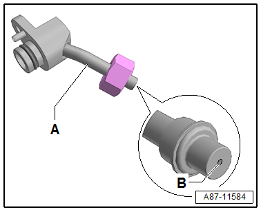
The restrictor creates a constriction. This restriction reduces the flow and creates high and low pressure sides in the refrigerant circuit. Before the restrictor the refrigerant which is under a higher pressure is warm. After the restrictor the refrigerant which is under a low pressure is cold.
Note
- The illustration shows a refrigerant line -A- with a fixed installed restrictor -B- (without a strainer)
- The diameter of the illustrated variable orifice -B- is approximately 0.7 mm. Depending on the version of the refrigerant line this constriction is either installed fixed in the refrigerant line or only inserted. For the inserted version a strainer for flowing deposits may be installed, which can be blocked by the variable orifice.
- Before installing check for debris and if necessary clean or replace.
- There are different versions, therefore pay attention to the different customer service information sources. Refer to → Heating, Ventilation and Air Conditioning; Rep. Gr.87; System Overview - Refrigerant Circuit and (vehicle-specific repair manual) and to the Parts Catalog.
Receiver/Dryer
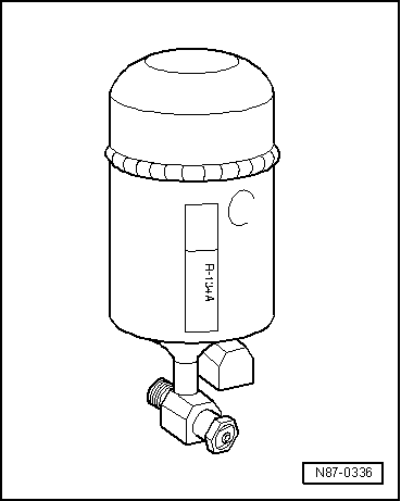
The receiver/dryer collects the fluid drops and then directs them in an uninterrupted stream to the expansion valve. Moisture which has entered the refrigerant circuit during repairs will be collected by the desiccant bag in the receiver/dryer.
Note
- Replace the receiver/dryer if refrigerant circuit has been open for a long time (beyond the normal repair time) and moisture has penetrated inside, or if required due to a specific complaint. Refer to → Chapter "Refrigerant Circuit Components, Replacing".
- Only remove sealing plugs shortly before installation.
- A desiccant bag in an unsealed receiver/dryer becomes saturated with moisture after a short period of time and unusable.
- When installing, note arrow for direction of flow if necessary.
- Depending on the version of the refrigerant circuit, the receiver/dryer is also installed (integrated) either on the condenser or inside the condenser. Refer to → Heating, Ventilation and Air Conditioning; Rep. Gr.87; System Overview - Refrigerant Circuit (vehicle-specific repair manual) and the Parts Catalog.
- The procedure is different for each complaint depending on the version of the receiver/dryer and the dryer cartridge. If the receiver/dryer, for example, is attached to the condenser, then it can be replaced complete with the drying cartridge. If the receiver/dryer, for example, is inside the condenser, then the dryer cartridge, and any possible additional filters, can be replaced separately, on most versions. If the receiver/dryer is inside the condenser and there is absolutely no way to replace the reservoir or the dry cartridge individually, then the entire condenser must be replaced. Refer to →Heating, Ventilation and Air Conditioning; Rep. Gr.87 and →Heating, Ventilation and Air Conditioning; Rep. Gr.87 (vehicle-specific repair manual) and Parts Catalog.
- Depending on the construction of the refrigerant circuit, the receiver can also be secured onto the condenser. Refer to → Heating, Ventilation and Air Conditioning; Rep. Gr.87; System Overview - Refrigerant Circuit (vehicle-specific repair manual) and the Parts Catalog.
READ NEXT:
 Expansion Valve
The expansion valve atomizes the streaming refrigerant and
controls the flow quantity so that the vapor is gaseous only at
the evaporator outlet, depending on the heat transmission.
Note
B
Quick-Release Connections on Refrigerant Lines
WARNING
The quick-release coupling connectors may be
unlocked and opened only if the refrigerant circuit is
empty.
Note
This illustration shows the quick-coupling connection with
Refrigerant Circuit
Refrigerant Circuit with Expansion Valve and Evaporator
The following illustration shows only the principle of a
refrigerant circuit, the design of the refrigerant circuit in
the respective vehicle
SEE MORE:
Gearshift Mechanism, Checking
WARNING
Risk of injury and accident by accidentally engaging
a selector lever position with the engine running.
Before working with the engine running, move the
transmission into "P" and pull the parking brake button
to activate the electro-mechanical parking brake.
Pay attention to t
Changing a tire
Preparation
You must complete the preparation before
changing a tire.
Read and follow the important safety precautions.
Set the parking brake.
Select the "P" selector lever position.
When towing a trailer: disconnect the trailer
from your vehicle.
Lay out the vehicle tool kit and the
spare t
