Audi A4: Front Peripheral Camera -R243-, Removing and Installing
The Front Peripheral Camera -R243- is installed in the radiator grille under the Audi rings.
Removing
- Turn off the ignition and all electrical equipment and remove the ignition key.
- Remove the front bumper cover. Refer to → Body Exterior; Rep. Gr.63; Front Bumper; Bumper Cover, Removing and Installing.
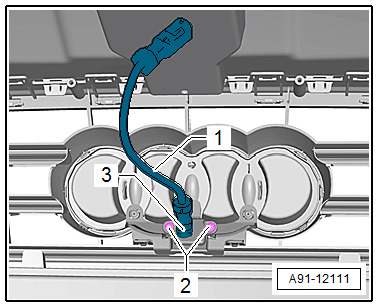
- Remove the screws -2- on the retaining plate for the Front Peripheral Camera -R243--3-.
- Remove the Front Peripheral Camera -R243--3- with the retaining plate from the front bumper cover.
- Release and disconnect the wire -1- from the Front Peripheral Camera -R243--3-.
Installing
- Install in reverse order of removal. Note the following:
- Perform the calibration. Refer to → Chapter "Peripheral Camera, Calibrating".
Tightening Specifications
.png)
Left/Right Peripheral Camera -R244-/-R245-, Removing and Installing
The Left Peripheral Camera -R244-/Right Peripheral Camera -R245- are located in the exterior rearview mirror respectively.
 Note
Note
The removal and installation is described for the left side. Removing and installing on the right side is identical.
Removing
- Turn off the ignition and all electrical equipment and remove the ignition key.
- Remove the exterior rearview mirror turn signal. Refer to → Electrical Equipment; Rep. Gr.94; Exterior Rearview Mirror Lamps; Turn Signal, Removing and Installing.
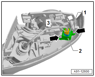
- Remove the bolts -arrows-.
- Remove the Left Peripheral Camera -R244--1- with the bracket -2- from the exterior rearview mirror.
- Release and disconnect the connector -3-.
- Remove the Left Peripheral Camera -R244--1- from the bracket -2-.
Installing
- Installation is identical in reverse order of removal.
Tightening Specifications
.png)
READ NEXT:
 Peripheral Camera, Calibrating
Calibration System -VAS721001-, Installing and Aligning
After performing service work on the vehicle, it may be
necessary to calibrate the peripheral camera system. In detail,
this is the case after
Mobile Online Services
Overview - Mobile Online Services
The mobile online service (1W3) consist of the eCall,
connected Gateway, and the Data Bus on Board Diagnostic
Interface -J533-.
The Data Bus on Board Diagnostic Int
SEE MORE:
Manually releasing the parking lock
Fig. 98 Front cup holder: removing the cover
Fig. 99 Front cup holder: parking lock emergency release
The emergency release is located in the front cup
holder under a cover.
You will need the screwdriver and the socket
wrench from the vehicle tool kit in order to release. Use the flat side of the
Steering Gear End Positions, Adapting
Special tools and workshop equipment required
Vehicle Diagnostic Tester
Note
If the connection between the steering gear and the steering
wheel is disconnected, the end position of the steering gear
must be readapted.
Procedure
- Connect the Vehicle Diagnostic Tester.
- Switch
