Audi A4: Electronic Damping
Component Location Overview - Electronic Damping
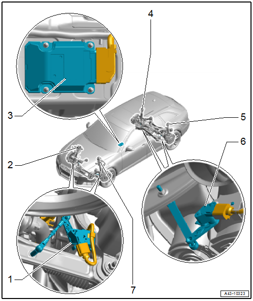
1 - Front Level Control System Sensor
- Left Front Level Control System Sensor -G78-
- Right Front Level Control Sensor -G289-
- Overview. Refer to → Chapter "Overview - Front Level Control System Sensor".
2 - Shock Absorber with Right Front Damping Adjustment Valve -N337-
- Overview. Refer to → Chapter "Overview - Suspension Strut Coil Spring".
3 - Drivetrain Control Module -J775-
- Installation location: On the center tunnel
- Removing and installing. Refer to → Chapter "Drivetrain Control Module -J775-, Removing and Installing".
4 - Shock Absorber with Right Rear Damping Adjustment Valve -N339-
- Overview. Refer to → Chapter "Overview - Shock Absorber".
5 - Shock Absorber with Left Rear Damping Adjustment Valve -N338-
- Overview. Refer to → Chapter "Overview - Shock Absorber".
6 - Rear Level Control System Sensor
- Left Rear Level Control System Sensor -G76-
- Right Rear Level Control System Sensor -G77-
- Overview. Refer to → Chapter "Overview - Rear Level Control System Sensor".
7 - Shock Absorber with Left Front Damping Adjustment Valve -N336-
- Overview. Refer to → Chapter "Overview - Suspension Strut Coil Spring".
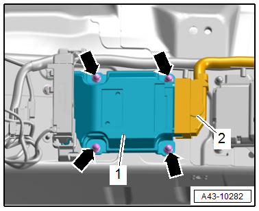
Electronic Damping Control Module -J250- - Tightening specification
- Tighten the nuts -arrows- to 8 Nm.
Electronic Damping Basic Setting
Adapting the height sensor end stops
Select this basic setting for the following operations:
- The threaded connection for a level control system sensor was loosened.
- A level control system sensor was removed and installed.
- A front or rear shock absorber was replaced.
Requirement:
- The vehicle must be raised on the hoist and the wheels are hanging freely, whereby the shock absorbers move into the end stops.
Adapting the height sensor zero position
Select this basic setting for the following operations:
- The threaded connection for a level control system sensor was loosened.
- A level control system sensor was removed and installed.
- The Drivetrain Control Module -J775- was removed and installed.
Requirements:
- The vehicle must be standing on a level surface.
- The vehicle may not be loaded.
Calibration of inertial sensors (sensors in control module)
Select this basic setting for the following operation:
- The Drivetrain Control Module -J775- was replaced
Requirements:
- The vehicle must be standing on a level surface.
- The vehicle may not be loaded.
 Note
Note
The basic settings can be done individually or together.
Procedure
- Connect the Vehicle Diagnostic Tester.
- Switch the ignition on.
- Select and start the Diagnostic operating mode.
- Select the Test plan tab.
- Select the Select individual test button and select the following tree structure consecutively:
- Chassis
- Suspension control
- 01 - OBD-capable systems
- 74 - Drivetrain Control Module J775
- 74 - Drivetrain Control Module Functions
- 74 - Basic setting
- Start the selected program and follow the instructions on the Vehicle Diagnostic Tester display.
The following procedures must be performed after a basic setting:
- Adjust the headlamps. Refer to → Electrical Equipment; Rep. Gr.94; Headlamps; Headlamps, Adjusting.
- Driver assistance systems front camera, calibrating. Refer to → Chapter "Driver Assistance Systems Front Camera, Calibrating".
Drivetrain Control Module -J775-, Removing and Installing
Special tools and workshop equipment required
- Vehicle Diagnostic Tester
Removing
- Remove the center console. Refer to → Body Interior; Rep. Gr.68; Center Console; Center Console, Removing and Installing.
- Remove the nuts -arrows-, and remove the Electronic Damping Control Module -J250--1-.
- Disconnect the connector -2-.
Installing
Install in reverse order of removal and note the following:
Activate the control module after installing a new Electronic Damping Control Module -J250-:
- Connect the Vehicle Diagnostic Tester.
- Switch the ignition on.
- Select and start the Diagnostic operating mode.
- Select the Test plan tab.
- Select the Select individual test button and select the following tree structure consecutively:
- Drivetrain
- Suspension control
- 01 - OBD-capable systems
- 74 - Drivetrain Control Module J775
- 74 - Drivetrain Control Module Functions
- 74 - Control module, replacing
- Start the selected program and follow the instructions on the Vehicle Diagnostic Tester display.
Tightening Specifications
- Refer to → Fig. " Electronic Damping Control Module -J250- - Tightening specification"
READ NEXT:
 Level Control System Sensor
Overview - Front Level Control System Sensor
1 - Bolt
9 Nm
2 - Front Level Control System Sensor
Left Front Level Control System Sensor -G78-
Right Front Level Control Syste
SEE MORE:
Tires and vehicle load limits
There are limits to the amount of
load or weight that any vehicle
and any tire can carry. A vehicle
that is overloaded will not handle well and is more difficult to stop.
Overloading can not only lead to
loss of vehicle control, but can also
damage important parts of the
vehicle and can lead to sudd
Operating the peripheral cameras
Applies to: vehicles with peripheral cameras
Fig. 129 Center display: peripheral cameras
On vehicles with peripheral cameras, you can select
among different views.
Selecting the views
To display the entire selection bar, tap the current
view (1) or swipe at the edge of the selection
bar from le
