Audi A4: Mobile Online Services
Overview - Mobile Online Services
The mobile online service (1W3) consist of the eCall, connected Gateway, and the Data Bus on Board Diagnostic Interface -J533-.
The Data Bus on Board Diagnostic Interface -J533- is installed under the rear bench seat for crash safety. The Data Bus on Board Diagnostic Interface -J533- contains an emergency module and a compass module. A separate SIM card is installed for the emergency call function and roadside assistance.
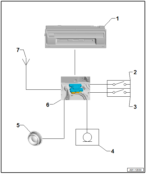
1 - Information Electronics Control Module 1 -J794- in the Glove Compartment
2 - Roadside Assistance Button -E275- in the Front Interior Lamp -W1-
3 - Emergency Call Button -E276- in the Front Interior Lamp -W1-
4 - Left Front Microphone -R140- in the Front Interior Lamp -W1-
5 - Emergency Call Module Speaker -R335- in the Driver Side Instrument Panel Cover
6 - Data Bus On Board Diagnostic Interface -J533- under the Rear Bench Seat
7 - GPS Antenna -R50- in the Roof Antenna -R216-
- Not on navigation, 7UG/7UH
- Emergency Module Antenna -R263- Under the Front Instrument Panel
Troubleshooting
The mobile online services system is capable of OBD.
Fault finding is performed using the "Guided Fault Finding" on the Vehicle Diagnostic Tester.
When there are concerns about the function, it necessary to be familiar with the Mobile Online Services functions.
For additional information. Refer to the Owner's Manual and → Wiring diagrams, Troubleshooting & Component locations.
Component Location Overview - Mobile Online Services
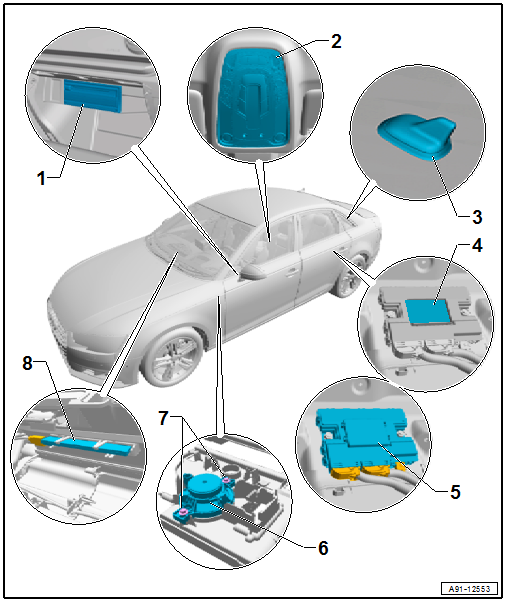
1 - Information Electronics Control Module 1 -J794-
- In the glove compartment
- Connector Assignment. Refer to → Wiring diagrams, Troubleshooting & Component locations.
- Removing and Installing. Refer to → Chapter "Information Electronics Control Module 1 -J794-, Removing and Installing".
2 - Front Interior Lamp -W1-
- with Roadside Assistance Button -E275-/Emergency Call Button -E276-/Left Front Microphone -R140-
- Removing and installing. Refer to → Electrical Equipment; Rep. Gr.96; Controls; Front Interior/Reading Lamp, Removing and Installing.
3 - GPS Antenna -R50-
- In the Roof Antenna -R216-
- Not on navigation, 7UG/7UH
4 - Telematics Emergency Battery -A16-
- With Data Bus on Board Diagnostic Interface -J533-
- Removing and installing. Refer to → Chapter "Telematics Emergency Battery -A16-, Removing and Installing".
5 - Data Bus on Board Diagnostic Interface -J533-
- Underneath the rear bench seat
- Connector Assignment. Refer to → Wiring diagrams, Troubleshooting & Component locations.
- Removing and installing. Refer to → Electrical Equipment; Rep. Gr.97; Control Module; Data Bus On Board Diagnostic Interface J533 Removing and Installing.
6 - Emergency Call Module Speaker -R335-
- In the driver side instrument panel cover
- Removing and installing. Refer to → Chapter "Emergency Call Module Speaker -R335-, Removing and Installing".
7 - Bolt
- 2 Nm
- Quantity: 2
8 - Emergency Module Antenna -R263-
- Under the front instrument panel
- Removing and installing. Refer to → Chapter "Emergency Module Antenna, Removing and Installing".
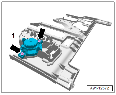
Emergency Call Module Speaker -R335-, Removing and Installing
The Emergency Call Module Speaker -R335- is located in the driver side instrument panel cover.
Removing
- Turn off the ignition and all electrical equipment and remove the ignition key.
- Remove the instrument panel cover on the driver side. Refer to → Body Interior; Rep. Gr.68; Compartment/Covers; Overview - Instrument Panel Cover on the Driver Side.
- Release and disconnect the connectors on the Emergency Call Module Speaker -R335-.
- Remove the bolts -arrows- on the Emergency Call Module Speaker -R335--1-.
- Remove the Emergency Call Module Speaker -R335--1- from the instrument panel cover.
Installing
- Install in reverse order of removal. Note the following:
Tightening Specifications
- Refer to → Chapter "Component Location Overview - Mobile Online Services"
Telematics Emergency Battery -A16-, Removing and Installing
Removing and Installing. Refer to Maintenance.
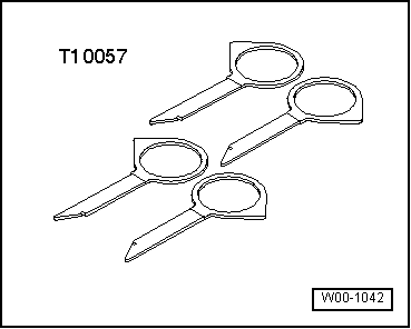
Special Tools
Special tools and workshop equipment required
- Radio Removal Tool -T10057-
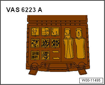
- Fiber-Optic Repair Set - Connector Protective Caps -VAS6223/9-.
- Calibration Tool - Wheel Center Mountings -VAS6350/1-
- Calibration Tool - Spacing Laser -VAS6350/2-
- Calibration Tool - Linear Laser -VAS6350/3-
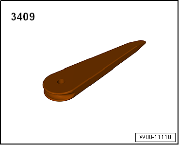
- Trim Removal Wedge -3409-
Revision History
DRUCK NUMBER: A005A012121
.png)
READ NEXT:
 Battery
Battery General Information
To guarantee a long service life, the Battery -A- must be
checked, serviced and maintained as described in this manual.
The Battery -A- supplies the power to start the eng
SEE MORE:
Exterior lighting
Switching the lights on and off
Fig. 42 Instrument panel: light switch with button
Light switch
Turn the light switch (1) to the corresponding position
when the ignition is switched on. The
symbol and the selected position will turn on (except
position 0).
O - The daytime running lights* will
Fuse assignment - footwell
Fig. 183 Driver's footwell (left-hand drive vehicle): fuse
panel with plastic clip
Fig. 184 Front passenger's footwell (right-hand drive vehicle):
fuse panel with plastic clip
Fuse panel (A) (brown)
Catalytic converter heating
Engine components
Exhaust doors, fuel injectors, air intake,
motor
