Audi A4: A/C Refrigerant High Pressure Switch -F23-
 Note
Note
Switch pressures, removing and installing switches as well as switch arrangement and version. Refer to vehicle specific refrigerant circuit → Heating, Ventilation and Air Conditioning; Rep. Gr.87; System Overview - Refrigerant Circuit (vehicle-specific repair manual).
Function:
Switches the coolant fan to the next higher level when the pressure in the refrigerant circuit increases (approximately 16 bar (232 psi) ).
Magnetic Clutch High Pressure Switch -F118-
Note
Switch pressures, removing and installing switches as well as switch arrangement and version. Refer to vehicle specific refrigerant circuit → Heating, Ventilation and Air Conditioning; Rep. Gr.87; System Overview - Refrigerant Circuit (vehicle-specific repair manual).
Function:
Switches off A/C compressor when there is excessive pressure in the refrigerant circuit (approximately 32 bar (464 psi) ).
A/C Refrigerant Low Pressure Switch -F73-
Note
Switch pressures, removing and installing switches as well as switch arrangement and version. Refer to vehicle specific refrigerant circuit → Heating, Ventilation and Air Conditioning; Rep. Gr.87; System Overview - Refrigerant Circuit (vehicle-specific repair manual).
Function:
Switches off A/C compressor when there is excessive pressure in the refrigerant circuit (approximately 2 bar (29 psi) ).
Refrigerant Circuit Connections with Valve for Switches
Note
Switch pressures, removing and installing switches as well as switch arrangement and version. Refer to vehicle specific refrigerant circuit → Heating, Ventilation and Air Conditioning; Rep. Gr.87; System Overview - Refrigerant Circuit (vehicle-specific repair manual).
- Different threads for switch on high pressure and low pressure sides.
- Only valves and O-ring seals that are resistant to refrigerant R134a and refrigerant oil must be installed.
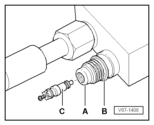
A - Connection (soldered in)
B - O-ring seal
C - Valve (with O-ring seal)
Note
To remove and install the valve insert -C- when the refrigerant circuit is discharged, use, for example, an adapter from the Refrigerant Sockets -T10364- (for the tightening specification. Refer to → Chapter "Connections with Schrader Valve (Needle Valve)").
READ NEXT:
 A/C Pressure Switch -F129-
Note
Switch pressures, removing and installing switches as well
as switch arrangement and version. Refer to vehicle specific
refrigerant circuit
→ Heating, Ventilation and Air Condit
A/C Pressure/Temperature Sensor
There are different versions of this sensor with different
functions and with different names. For exact name, allocation
and notes doe the respective function, refer to
→ Heating, Ventilatio
Refrigerant Circuit Pressures and Temperatures
General Information
Caution
When performing work on refrigerant circuit, observe
all generally applicable safety precautions and pressure
container regulations.
The pressures and temperatur
SEE MORE:
Indicator lights overview
Description
The indicator lights in the instrument cluster
blink or turn on. They indicate functions or malfunctions.
Some warning and indicator lights
turn on when you switch the ignition on and must turn off when the drive system
is switched on or
while driving.
With some indicator lights, mess
Front Midrange Speaker, Removing and Installing
The Left Front Midrange Speaker -R103-/Right Front Midrange
Speaker -R104--1- are located in
the center of the front doors.
Removing and installing is identical.
Removing
- Turn off the ignition and all electrical equipment and
remove the ignition key.
- Remove the front door trim panel
