Audi A4: Peripheral Camera, Calibrating
Calibration System -VAS721001-, Installing and Aligning
After performing service work on the vehicle, it may be necessary to calibrate the peripheral camera system. In detail, this is the case after:
- Replacing one or more cameras
- Peripheral Camera Control Module -J928- replacement
- Flash the software from the Peripheral Camera Control Module -J928-
- Record the data set on the Peripheral Camera Control Module -J928-
- Repair work on components in which a camera is installed or that influence the component location of the camera
- Wheel alignments
- When adjusting the overlap range of the individual cameras
- The standing height of one axle changes by more than 5 mm
- The standing height of the entire vehicle changes by more than 10 mm (0.39 in.)
Requirement for the Calibration of the Vehicle
- Camera lens must be cleaned, only clean the camera lenses with a wet towel.
- Check the camera images on the Front Information Display Control Head -J685-. Replace the camera if the images are unclear because the camera has been damaged. Check the fastener for the camera if the image is low.
- Make sure both exterior rearview mirrors are folded out.
- The parking brake must be set.
- The steering wheel must be in the 0 position and the wheels must be straight.
- All doors and the rear lid must be closed.
- No one should be in the vehicle.
- The vehicle must not be loaded (curb weight).
- The battery charger is connected, the battery charger must not be in the view of the camera.
- Ignition switched on.
- The system is active and is displayed on the Front Information Display Control Head -J685-.
- Do not move the vehicle during the calibration process.
Requirements for the Calibration Equipment/Calibration Environment
- Flat calibration surface
- Do not use any objects in the environment of the calibration field, to prevent a false recognition of lines
- Even light (no headlamps or direct illumination), prevent strong light differences
Special tools and workshop equipment required
- Calibration System -VAS721001-
- Vehicle Diagnostic Tester
Overview of the Installed Calibration System -VAS721001-.
 WARNING
Make sure light does not reflect off the Calibration System -VAS721001-.
Reflections affect the camera and may make it impossible to perform the calibration.
 Note
Note
The vehicle in the illustration is only a basic outline.
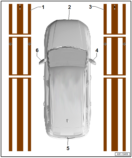
1 - Left Calibration Device
2 - Front Peripheral Camera -R243-
- Calibrating. Refer to → Chapter "Peripheral Camera System, Calibrating".
3 - Right Calibration Device
4 - Right Peripheral Camera -R245-
- Calibrating. Refer to → Chapter "Peripheral Camera System, Calibrating".
5 - Rear Peripheral Camera -R246-
- Calibrating. Refer to → Chapter "Peripheral Camera System, Calibrating".
6 - Left Peripheral Camera -R244-
- Calibrating. Refer to → Chapter "Peripheral Camera System, Calibrating".
Peripheral Camera System, Calibrating
- The vehicle must be on a level surface.
Note
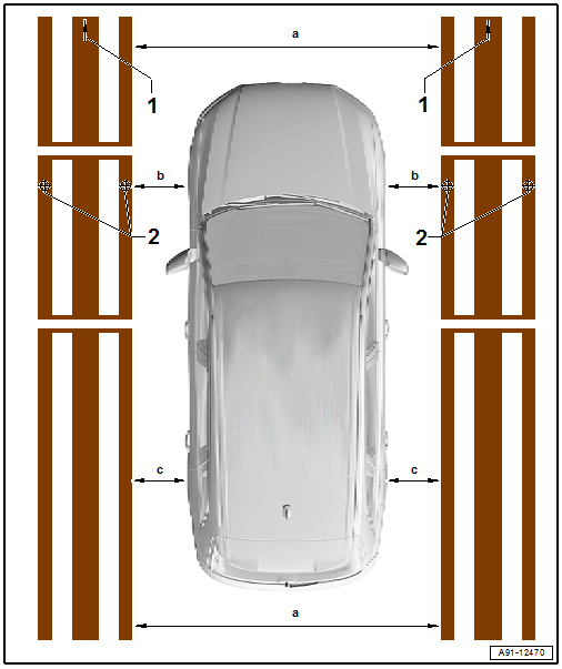
The vehicle in the illustration is only a basic outline.
- Roll out the Calibration System -VAS721001- at the left and right near the vehicle.
- Install the rear and front clamping strip on the Calibration System -VAS721001-.
- Align the crosshairs -2- to the front axle of the vehicle (center front wheel).
- Align both calibration devices parallel. The vehicle must be located in the center between both calibration devices.
Pay attention to the following measurement requirements:
- Dimension -a- 2000 to 2500 mm +- 2 mm (78.74 to 98.4 +- 0.07 in.), front and rear the same
- The dimension -b- must be the same on both sides
- The dimension -c- must be the same on both sides
- Set-up the requirement for the vehicle.
- Connect the Vehicle Diagnostic Tester.
Calibrating Procedure
- Select the Diagnostic mode and start the diagnosis.
- Select the Test plan tab.
- Press the Select individual test button and select the following one after the other:
- Body
- Electrical Equipment
- 01 - OBD-capable systems
- 6C - Peripheral camera control module | J928
- 6C - Peripheral camera control module, functions
- 6C - Calibration, (Repair Group 91)
From here, the Vehicle Diagnostic Tester advances the calibration procedure forward.
WARNING
Make sure light does not reflect off the Peripheral Camera Calibration Device -VAS6350/6-.
Reflections affect the camera and may make it impossible to perform the calibration.
READ NEXT:
 Mobile Online Services
Overview - Mobile Online Services
The mobile online service (1W3) consist of the eCall,
connected Gateway, and the Data Bus on Board Diagnostic
Interface -J533-.
The Data Bus on Board Diagnostic Int
SEE MORE:
Door Windows
Overview - Front Door Window
1 -
Window Regulator
Overview. Refer to
→ Chapter "Overview - Window Regulator".
2 -
Door Window
Removing and installing. Refer to
→ Chapter "Front Door Window, Removing and Installing".
Overview - Rear Door Window
1 -&nbs
Overview - Drive Axle
1 - Cap
Carefully drive off using a drift
Replace if damaged
Adhesive surface must be free of oil and grease
Coat the sealing surface with Sealant -D 454 300 A2- before installing on
CV joint.
2 - Circlip
Replace after removing
Insert in shaft groove
3 - In
