Audi A4: Vehicle Diagnosis, Testing and Information Systems
 WARNING
- During road tests using a vehicle diagnostic and information system, there is the hazard of extreme to lethal injuries!
- If vehicle diagnostic and information system is deposited in the action area of an airbag during a road test, here is the hazard of extreme to lethal injuries in the event the airbag deploys!
- During road tests, have a person sitting in the rear seat to operate the vehicle diagnostic and information system.
Audi TT and Audi R8
WARNING
- During road tests using a Vehicle Diagnostic Tester, there is the hazard of extreme to lethal injuries!
- If vehicle diagnostic and information system is deposited in the action area of an airbag during a road test, here is the hazard of extreme to lethal injuries in the event the airbag deploys!
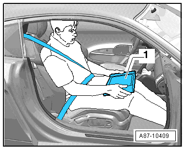
- During road tests, have a person sitting in the front passenger seat in the rearmost position to operate the Vehicle Diagnostic Tester.
- TheVehicle Diagnostic Tester-1- must lie flat on the passenger's legs and be operated by that person, as shown in the illustration.
- Connect the Vehicle Diagnostic Tester. Refer to → Chapter "Vehicle Diagnostic Tester, Connecting".
Vehicle Diagnostic Tester, Connecting
Special tools and workshop equipment required
- Vehicle Diagnostic Tester and diagnostic cable
Procedure
- Engage the parking brake or operate the electromechanical parking brake.
- Shift the shifter lever into neutral or place the selector lever in the "P" position.
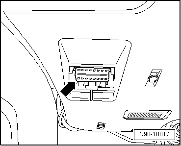
- Turn off the ignition and connect the Vehicle Diagnostic Tester to the Data Link Connector (DLC) with the diagnostic cable -arrow-.
- When using the Remote Diagnosis Head -VAS5054A- or the Diagnosis Interface -VAS5055- pay attention to the Operating Instructions.
- Turn on the ignition.
- Turn off all electrical consumers.
 Note
Note
If a error message appears on the screen of the Vehicle Diagnostic Tester. Refer to the Operating Instructions.
READ NEXT:
 Wiring Harness and Connector Repairs
Vehicle Electrical System, General Repair Information
Caution
When disconnecting and connecting battery, the
procedure must be followed as described in the Repair
Manual.
WARNING
S
Wiring Harness Repair Set
Wiring Harness Repair Set -VAS1978-
The Wiring Harness Repair Set -VAS1978- makes optimal repair
quality possible in the realm of vehicle electronics. Using the
tools, repairs affecting harness conn
Tool Descriptions
Crimping Pliers with Insert
The Crimping Pliers without Insert -VAS1978/1- with Crimping
Pliers - Insert 2 -VAS1978/2- is a component of the Wiring
Harness Repair Set -VAS1978- and is used to crimp
SEE MORE:
Seat Belts
Component Location Overview - Seat Belts and Mounting Points
Note
The Avant is shown.
1 - Front Belt End Fitting
Overview. Refer to
→ Chapter "Overview - Front Three-Point Seat Belt".
2 - Automatic Belt Retractor
For the front three-point seat belt
With:
General Information
Vehicles with a High Voltage System (Hybrid Vehicles)
Extremely Dangerous Due to High-Voltage
The high-voltage system is under high-voltage. Death or serious
bodily injury by electric shock.
- Individuals with electronic/medical life- and health sustaining
machines in or on their person canno
