Audi A4: DSG Transmission Mechatronic -J743-
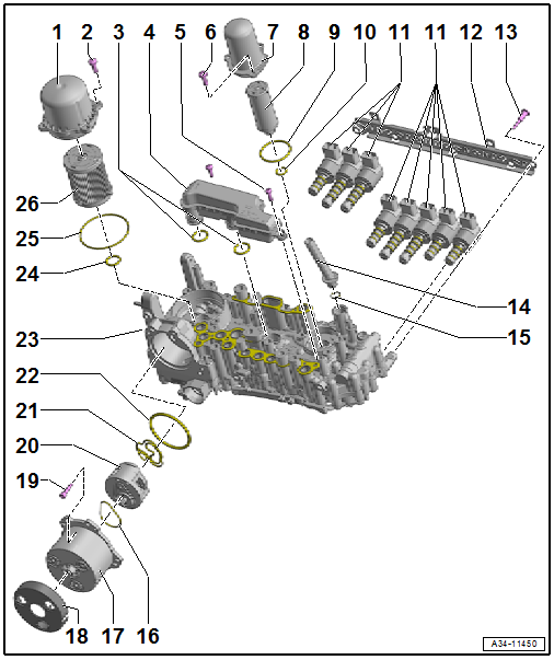
Overview - Mechatronic
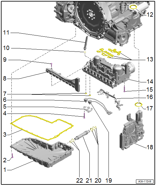
1 - Transmission Fluid Pan
- Removing and installing. Refer to → Chapter "Transmission Fluid Pan, Removing and Installing".
2 - Bolt
- Tightening specification and sequence. Refer to → Fig. "Transmission Fluid Pan - Tightening Specification and Sequence".
3 - Seal
- Replace after removing.
4 - Bolt
- Tightening specification and sequence. Refer to → Fig. " Hydraulic Pressure Sensor 1 -G545- and Hydraulic Pressure Sensor 2 -G546- - tightening specification and sequence".
5 - Bracket
6 - Hydraulic Pressure Sensor 2 -G546-
- Removing and installing. Refer to → Chapter "Hydraulic Pressure Sensor 1 -G545- and Hydraulic Pressure Sensor 2 -G546-, Removing and Installing".
7 - Seals
8 - Contact Element
9 - Bolt
10 - O-Ring
- Replace after removing.
11 - Bleed Pipe
12 - Dust Ring
13 - Seals
- Replace after removing.
14 - Mechatronic
- Removing an installing. Refer to → Chapter "Mechatronic, Removing and Installing".
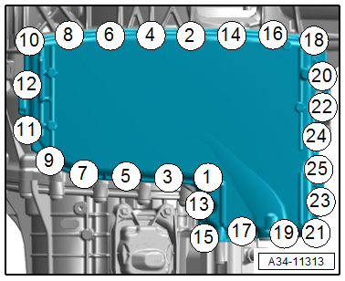
15 - Mechatronic Bolts. Refer to → Fig. "Mechatronic - Tightening Specification and Sequence".
16 - Wiring Guide
- Replace after removing.
17 - Seal
- Replace after removing.
18 - Transmission Control Module -J217-
19 - Hydraulic Pressure Sensor 1 -G545-
- Removing and installing. Refer to → Chapter "Hydraulic Pressure Sensor 1 -G545- and Hydraulic Pressure Sensor 2 -G546-, Removing and Installing".
20 - O-Rings
- Replace after removing.
21 - ATF Pipe
- Replace after removing.
22 - Seals
- Replace after removing.
Transmission Fluid Pan - Tightening Specification and Sequence
.png)
Mechatronic - Tightening Specification and Sequence
.png)
Hydraulic Pressure Sensor 1 -G545- and Hydraulic Pressure Sensor 2 -G546- - tightening specification and sequence
.png)
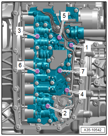
Overview - Valve Body
1 - Low Pressure Filter Housing
2 - Bolt
- Quantity: 4
- M6 × 20
3 - Seal
4 - Suction Filter
5 - Bolt
- Quantity: 2
- M5 × 18
6 - Bolt
- Quantity: 3
- M6 × 20
7 - High Pressure Filter Housing
8 - High Pressure Filter
9 - Seal
10 - Seal
11 - Valve Units
12 - Valve Unit Retainer
13 - Bolt
- Quantity: 8
- M4 × 35
14 - Bleed Pipe
15 - Seal
16 - Seal
17 - Transmission Fluid Auxiliary Hydraulic Pump -V552- Motor
- Removing and installing. Refer to → Chapter "Transmission Fluid Auxiliary Hydraulic Pump -V552-, Removing and Installing".
18 - Cover
19 - Bolt
- 4 Nm + 45º
- M5 × 22
- Quantity: 4
20 - Transmission Fluid Auxiliary Hydraulic Pump -V552- Pump
- Removing and installing. Refer to → Chapter "Transmission Fluid Auxiliary Hydraulic Pump -V552-, Removing and Installing".
21 - Seal
22 - Seal
23 - Valve Body
- Removing and installing Transmission Control Module - J217- removing. Refer to → Chapter "Transmission Control Module -J217-, Removing and Installing".
24 - Seal
25 - Seal
26 - Low Pressure Switch
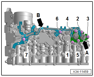
Overview - Transmission Control Module -J217-
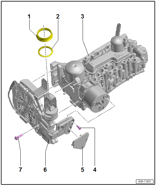
1 - Seal
2 - Seal
- Replace after removing.
3 - Valve Body
- Refer to → Chapter "Overview - Valve Body".
4 - Bolt
- 5 Nm +20º
- Replacing
- Quantity: 3
5 - Cover
6 - Transmission Control Module -J217-
- Removing and installing. Refer to → Chapter "Transmission Control Module -J217-, Removing and Installing".
7 - Bolt
- 3 Nm +90º
- Replacing
- Quantity: 4
READ NEXT:
 Transmission Fluid Pan, Removing and Installing
Special tools and workshop equipment required
Engine Bung Set -VAS6122-
Used Oil Collection and Extraction Unit -SMN372500-
Removing
Note
General repair instructions. Refer to
→
Mechatronic, Removing and Installing
Special tools and workshop equipment required
Used Oil Collection and Extraction Unit -SMN372500-
Assembly Tool -T40305-
Oil Sump Assembly Pin -T40199-
Electronic Torque Wrench 3-60Nm -VAS6583-
Transmission Control Module -J217-, Removing and Installing
Removing
WARNING
The system is under pressure.
The electronic ATF pump must be deactivated every
time before opening the transmission, and the hydraulic
pressure reservoir is drained.
Re
SEE MORE:
Stabilizer Bar, Removing and Installing
Special tools and workshop equipment required
Torque Wrench 1331 5-50Nm -VAG1331-
Caution
This procedure contains mandatory replaceable parts.
Refer to component overview and parts catalog prior to
starting procedure.
Mandatory Replacement Parts
Nut - Stabilizer Bar to Coupling Rod
Child Seat Anchors
Overview - Front Child Seat Anchors
1 - Child Seat Anchor
Front passenger seat only
Bolted to the seat pan
Check after an accident. Refer to
→ Chapter "Child Seat Anchors, Checking After Collision".
Replace damaged or deformed child seat anchor
Removing and installing. Refer
