Audi A4: Mechatronic, Removing and Installing
Special tools and workshop equipment required
- Used Oil Collection and Extraction Unit -SMN372500-
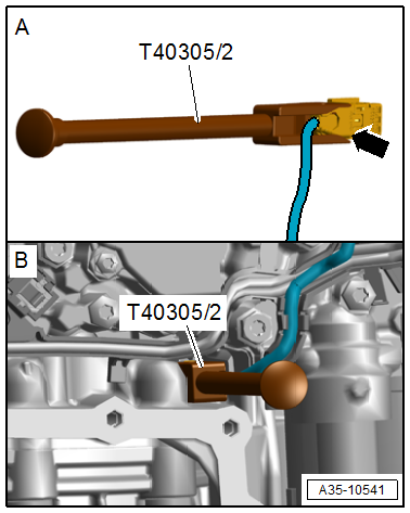
- Assembly Tool -T40305-
- Oil Sump Assembly Pin -T40199-
- Electronic Torque Wrench 3-60Nm -VAS6583-
- Cover -T40322-
- Support -T40321-
Removing
 Note
Note
- General repair instructions. Refer to → Chapter "Repair Information".
- Guidelines for clean working conditions when working on the dual-clutch transmission. Refer to → Chapter "Rules for Cleanliness When Working on DSG Transmission".
 WARNING
The system is under pressure.
- Deactivate the ATF pump and drain the hydraulic pressure reservoir before removing the Mechatronic!
- Refer to → Chapter "ATF Pump, Deactivating and Draining the Hydraulic Pump Reservoir".
 Caution
There is a risk of destroying the transmission control module (Mechatronic) with static discharge.
- Always "discharge" the static electricity before working with connectors. Do this by touching a grounded object, for example vehicle ground, the heater or the hoist.
- Do not touch connector terminals in the transmission connector with hands.
The Transmission is Installed.
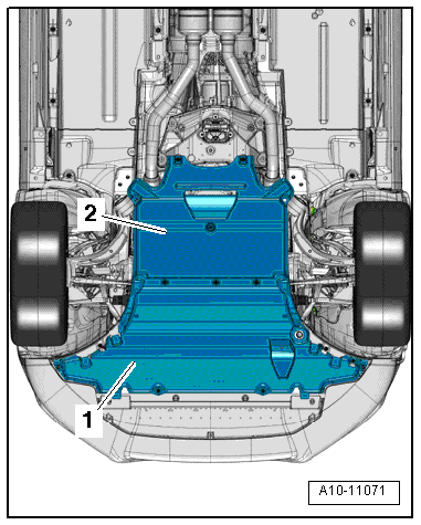
- Remove the noise insulations -1 and 2-. Refer to → Body Exterior; Rep. Gr.66; Noise Insulation.
- Drain the ATF. Refer to → 7-Speed Dual Clutch Transmission 0CK; Rep. Gr.34; ATF; ATF, Draining and Filling.
- Turn off the ignition and remove the key.
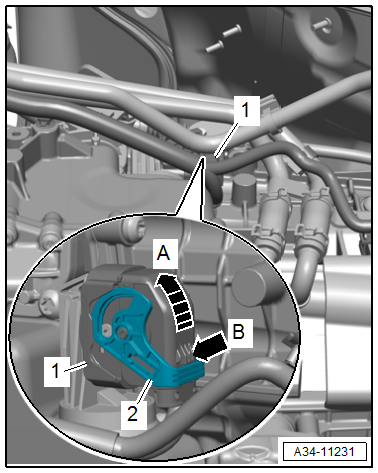
- Disconnect the connector -1- by pressing the locking mechanism -B arrow- and pull the locking bracket -2- in the direction of -arrow A-.
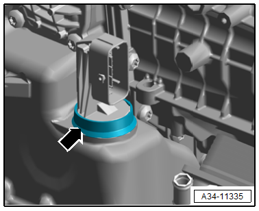
- Remove the protective cap -arrow-.
- Remove the transmission fluid pan. Refer to → Chapter "Transmission Fluid Pan, Removing and Installing".
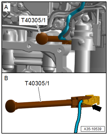
- Disconnect the connector -arrow- using the Assembly Tool -T40305-.
WARNING
The system may be under pressure.
- Make sure that the ATF pressure reservoir is discharged. Refer to → Chapter "ATF Pump, Deactivating and Draining the Hydraulic Pump Reservoir".
- When the system status is not clear, for example the cause of a faulty transmission control module, only loosen the mechatronic bolts to a minimal degree, so that the oil pressure in the hydraulic pressure reservoir can decrease slowly.
- Wear protective eyewear.
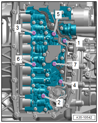
- Loosen the bolt in the sequence -1 to 7- a 1/2 turn.
- Remove the bolts -2 and 5- and install the two Oil Sump Assembly Pin -T40199- in their place.
- Remove the remaining bolts -1, 3, 4, 6 and 7-.
Caution
Risk of causing damage to the Mechatronic.
- Only bolts -1 through 7- may be loosened.
- If other bolts are loosened, this may impair the function of the Mechatronic unit or it may come apart.
Note
- The Mechatronic fits partially inside the transmission.
- If the Mechatronic must be removed, then a second technician will be needed to keep it from falling. Another alternative, the bolts -1 and 2- can be installed slightly to hold the Mechatronic in place while it is being removed.
Caution
Risk of causing damage to the Mechatronic.
Lay the Mechatronic with the bolt head side facing down only.
- Remove the Mechatronic.
Caution
Contamination damages the Mechatronic.
A clean work environment is required for working on the Mechatronic.
- Place the removed Mechatronic on a clean surface and cover it. Use foil or lint-free cloths.
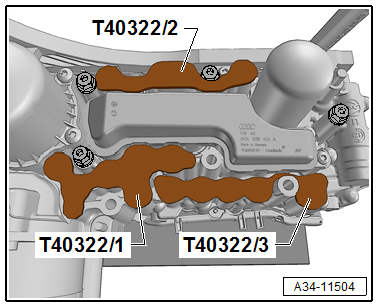
- Seal the ATF channel with the Cover -T40322-.
Installing
Install in the reverse order of removal while noting the following:
Caution
- The pump for the Transmission Fluid Auxiliary Hydraulic Pump -V552- can start up on a non-deactivated control module immediately after installing the connector. Refer to → Chapter "ATF Pump, Deactivating and Draining the Hydraulic Pump Reservoir".
- From this the pump can be damaged, or the residual oil can flow out under high pressure.
- To prevent this install the transmission control module connector after installing the oil pan and the transmission filled with ATF.
- Only install clean parts: remove the new mechatronic from the packaging immediately prior to installation.
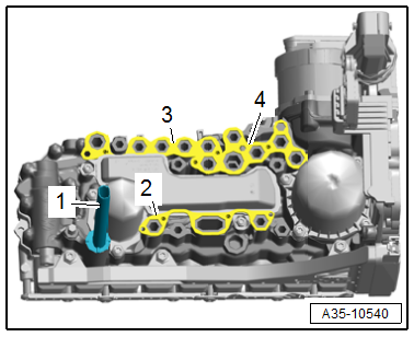
- Replace the seals -2, 3 and 4-.
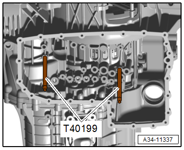
- Install the two Oil Sump Assembly Pin -T40199- hand-tight as illustrated.
Note
The Oil Sump Assembly Pin -T40199- prevent the Mechatronic from tilting when it is being installed.
- Replace the Mechatronic evenly and install the bolts -6 and 7- hand-tight.
- Remove the Oil Sump Assembly Pin -T40199-.
- Install the remaining bolts according to the tightening sequence. Refer to → Fig. "Mechatronic - Tightening Specification and Sequence".
- Install the connector with the Assembly Tool -T40305-.
- Install the transmission fluid pan. Refer to → Chapter "Transmission Fluid Pan, Removing and Installing".
Install the oil pan with a new seal and tighten to the tightening specification. Refer to → Fig. "Transmission Fluid Pan - Tightening Specification and Sequence".
- Fill the ATF. Refer to → 7-Speed Dual Clutch Transmission 0CK; Rep. Gr.34; ATF; ATF, Draining and Filling.
Note
- If the control module or the mechatronic is replaced, only prefill the ATF. (Filling quantity 3.5 liters (3.69 quarts) )
- The ATF level can be adjusted after operating the control module.
- After working on the DSG Transmission Mechatronic -J743- the function "control module, replacing" must be performed. Refer to Vehicle Diagnostic Tester.
Procedure
- Connect the Vehicle Diagnostic Tester.
- Select Diagnostic mode and start the diagnostic.
- Select the Test plan tab.
- Select individual test button and select the following tree structure one after the other:
- Drivetrain
- 7-Speed Dual Clutch Transmission 0CK/0CL
- 01 - OBD-capable systems
- 02 - Transmission electronics 0CK
- 02 - Transmission electronics, functions
- 02 - Control module, replacing
- Checking the ATF level. Refer to → 7-Speed Dual Clutch Transmission 0CK; Rep. Gr.34; ATF; ATF Level, Checking.
- Install the noise insulation. Refer to → Body Exterior; Rep. Gr.66; Noise Insulation.
READ NEXT:
 Transmission Control Module -J217-, Removing and Installing
Removing
WARNING
The system is under pressure.
The electronic ATF pump must be deactivated every
time before opening the transmission, and the hydraulic
pressure reservoir is drained.
Re
Hydraulic Pressure Sensor 1 -G545- and Hydraulic Pressure Sensor 2 -G546-,
Removing and Installing
Note
The Mechatronic remains installed.
WARNING
The system is under pressure.
The electronic ATF pump must be deactivated every
time before opening the transmission, and the hydrau
Special Tools
Special tools and workshop equipment required
Used Oil Collection and Extraction Unit -SMN372500-
Locking Pin -T10492-
Retaining Strap -T40155-
Oil Sump Assembly Pin -T40199-
Gearbox
SEE MORE:
System settings
Introduction
General settings are described in this chapter.
You can find specific settings in the chapters
about those settings. The available settings depend
on the vehicle equipment.
Date and time
Applies to: MMI: Select on the home screen:
SETTINGS > General > Date & time.
Possibl
Door Lock, Removing and Installing
NOTICE
Risk of damaging the operating cable by deforming it.
- Never sharply bend or kink the operating cable.
Removing
- Move the door window into the "closed" position.
- Remove the door inner cover. Refer to
→ Chapter "Door Inner Cover, Removing and Installing".
-&n
