Audi A4: Mechatronic
Overview - Mechatronic
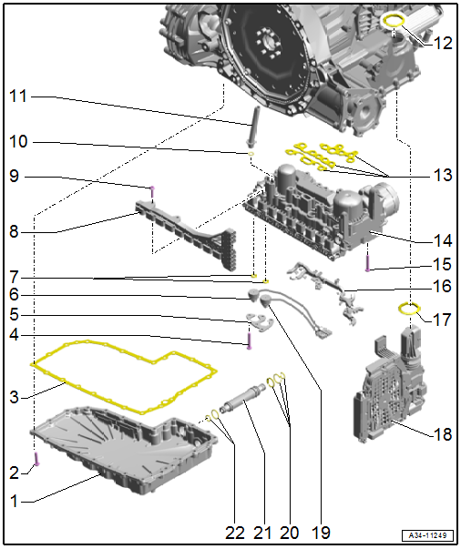
1 - Transmission Fluid Pan
- Removing and installing. Refer to → Chapter "Transmission Fluid Pan, Removing and Installing".
- Aluminum or plastic
2 - Bolt
- Tightening specification and sequence. Refer to → Fig. "Transmission Fluid Pan - Tightening Specification and Sequence".
3 - Seal
- Replace after removing
4 - Bolt
- Tightening specification. Refer to → Servicing - 7-Speed Dual Clutch Transmission 0CJ, 0CK, 0CL; Rep. Gr.34; Mechatronic; Overview - Mechatronic.
5 - Bracket
6 - Hydraulic Pressure Sensor 2 -G546-
- Removing and installing. Refer to → Servicing - 7-Speed Dual Clutch Transmission 0CJ, 0CK, 0CL; Rep. Gr.34; Mechatronic; Overview - Mechatronic.
7 - O-Rings
- Replace after removing
8 - Contact Element
9 - Bolt
- Tightening specification. Refer to → Servicing - 7-Speed Dual Clutch Transmission 0CJ, 0CK, 0CL; Rep. Gr.34; Mechatronic; Overview - Mechatronic.
10 - O-Ring
- Replace after removing
11 - Bleed Pipe
12 - Dust Ring
13 - Seals
- Replace after removing
14 - Mechatronic
- Removing and installing. Refer to → Chapter "Mechatronic, Removing and Installing".
15 - Mechatronic Bolt. Refer to → Servicing - 7-Speed Dual Clutch Transmission 0CJ, 0CK, 0CL; Rep. Gr.34; Mechatronic; Overview - Mechatronic.
16 - Wiring Guide
17 - Seal
- Replace after removing
18 - Transmission Control Module -J217-
- Removing and installing. Refer to → Servicing - 7-Speed Dual Clutch Transmission 0CJ, 0CK, 0CL; Rep. Gr.34; Mechatronic; Overview - Mechatronic.
19 - Hydraulic Pressure Sensor 1 -G545-
- Removing and installing. Refer to → Servicing - 7-Speed Dual Clutch Transmission 0CJ, 0CK, 0CL; Rep. Gr.34; Mechatronic; Overview - Mechatronic.
20 - O-Rings
- Replace after removing
21 - ATF Pipe
- Replace after removing
22 - Seals
- Replace after removing
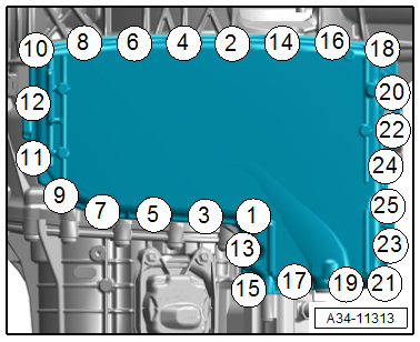
Transmission Fluid Pan - Tightening Specification and Sequence
- Tighten the bolts in steps according to the specified sequence:
.png)
Transmission Fluid Pan, Removing and Installing
Special tools and workshop equipment required
- Vehicle Diagnostic Tester
- Engine Bung Set -VAS6122-
- Used Oil Collection and Extraction Unit -SMN372500-
Removing
 Caution
Risk of damaging the transmission.
Do not run engine or tow vehicle when the transmission fluid pan is removed or without transmission fluid.
 WARNING
The system is under pressure.
Deactivate the ATF pump and drain the hydraulic pressure reservoir before removing the transmission fluid pan!
- Using the Vehicle Diagnostic Tester in the Transmission Control Module -J217- empty the ATF pressure reservoir and disable the Transmission Fluid Auxiliary Hydraulic Pump -V552-. Refer to → Chapter "ATF Pump, Deactivating and Draining the Hydraulic Pump Reservoir".
- Remove the ATF cooler. Refer to → Chapter "ATF Cooler, Removing and Installing".
- Remove the subframe crossbrace. Refer to → Suspension, Wheels, Steering; Rep. Gr.40; Subframe; Subframe Crossbrace, Removing and Installing.
- Remove the bolts in the sequence -25 to 1- and remove the transmission fluid pan.
Installing
Install in the reverse order of removal while noting the following:
 Note
Note
Replace the seal and ATF pipe after removal.
- Install the ATF cooler. Refer to → Chapter "ATF Cooler, Removing and Installing".
Tightening Specifications
- Refer to → Fig. "Transmission Fluid Pan - Tightening Specification and Sequence"
- Refer to → Suspension, Wheels Steering; Rep. Gr.40; Subframe; Overview - Subframe.
Mechatronic, Removing and Installing
Special tools and workshop equipment required
- Vehicle Diagnostic Tester
Removing
WARNING
The system is under pressure.
Deactivate the ATF pump and drain the hydraulic pressure reservoir before removing the transmission fluid pan!
- Using the Vehicle Diagnostic Tester in the Transmission Control Module -J217- empty the ATF pressure reservoir and disable the Transmission Fluid Auxiliary Hydraulic Pump -V552-. Refer to → Chapter "ATF Pump, Deactivating and Draining the Hydraulic Pump Reservoir".
- Remove the subframe crossbrace. Refer to → Suspension, Wheels, Steering; Rep. Gr.40; Subframe; Subframe Crossbrace, Removing and Installing.
- Remove the transmission fluid pan. → Chapter "Transmission Fluid Pan, Removing and Installing".
Refer to → Servicing - 7-Speed Dual Clutch Transmission 0CJ, 0CL, 0CK; Rep. Gr.34; Mechatronic; Mechatronic, Removing and Installing for all further work on the Mechatronic.
Installing
Install in reverse order of removal.
Tightening Specifications
- Refer to → Chapter "Overview - Mechatronic"
- Refer to → Suspension, Wheels Steering; Rep. Gr.40; Subframe; Overview - Subframe.
READ NEXT:
 Special Tools
Special tools and workshop equipment required
Used Oil Collection and Extraction Unit -SMN372500-
Tensioning Strap -T10038-
Seal Installer - Selector Shaft -T10135-
Engine/Gearbox Jack -
Transmission Control
Component Location Overview - Transmission Control
1 - DSG Transmission Mechatronic -J743-
Removing and installing. Refer to
→ Chapter "Mechatronic, Removing and Installing".
2&n
SEE MORE:
Parking aid plus
Activating and deactivating
Applies to: vehicles with parking aid plus
Fig. 124 Center console: parking aid button
General information
The parking aid assists when parking and maneuvering
by providing warnings about obstacles. If
the ultrasonic sensors on the vehicle,
fig. 100 detect an obstacle, t
Refrigerant Circuit
Refrigerant Circuit with Expansion Valve and Evaporator
The following illustration shows only the principle of a
refrigerant circuit, the design of the refrigerant circuit in
the respective vehicle can be found in the vehicle-specific
repair manual. Refer to
→ Heating, Ventilation and Air
