Audi A4: Transmission Control Module -J217-, Removing and Installing
Removing
 WARNING
The system is under pressure.
- The electronic ATF pump must be deactivated every time before opening the transmission, and the hydraulic pressure reservoir is drained.
- Refer to → Chapter "ATF Pump, Deactivating and Draining the Hydraulic Pump Reservoir".
 Note
Note
- General repair instructions. Refer to → Chapter "Repair Information".
- Guidelines for clean working conditions when working on the dual-clutch transmission. Refer to → Chapter "Rules for Cleanliness When Working on DSG Transmission".
- Disable the ATF pump and drain the pressure reservoir. Refer to → Chapter "ATF Pump, Deactivating and Draining the Hydraulic Pump Reservoir".
 Caution
Risk of destroying Transmission Control Module -J217- with static discharge.
- Always "discharge" the static electricity before working with connectors. Do this by touching a grounded object, for example vehicle ground, the heater or the hoist.
- Do not touch connector terminals in the transmission connector with hands.
- Remove the transmission fluid pan. Refer to → Chapter "Transmission Fluid Pan, Removing and Installing".
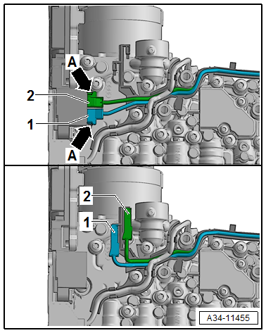
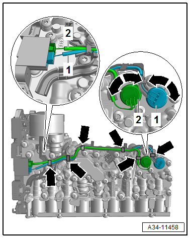
- Release the connector for the Hydraulic Pressure Sensor 1 - G545--1- and Hydraulic Pressure Sensor 2 -G546--2- at the retaining tabs -arrows- and disconnect from the Transmission Control Module -J217-.
- Secure the connector as shown in the designated transportation safeguard.
- Remove the Mechatronic. Refer to → Chapter "Mechatronic, Removing and Installing".
Caution
Contamination damages the Mechatronic.
A clean work environment is required for working on the Mechatronic.
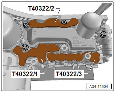
- Seal the ATF channel with the Cover -T40322-.
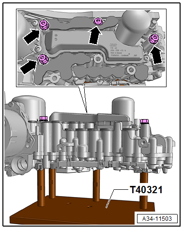
- Secure the Mechatronic on the Retaining Bracket.
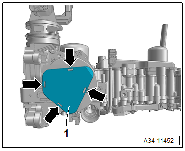
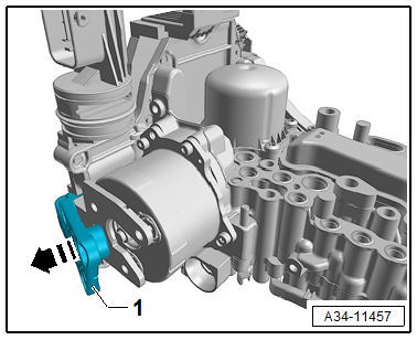
- Release the cover -1- for the sensor from the retaining tabs -arrows- and remove.
- Remove the bolts in the sequence -3 to 1-.
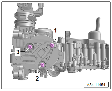
- Pivot the Transmission Fluid Auxiliary Hydraulic Pump Rotor Position Sensor -G847--1- to the side to the engagement position.
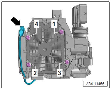
- Engage the connector for the Gear Position Distance Sensor 1 -G487- and Gear Position Distance Sensor 2 -G488- in the transportation safeguard -arrow- and loosen the bolts in the sequence -4 to 1-.
- Remove the Transmission Control Module -J217- from the valve body.
Installing
Install in the reverse order of removal while noting the following:
Note
Before installing clean the control module threaded holes of oil and debris.
- Push the control module evenly on the valve body and tighten the bolts in the sequence -1 to 4- to the tightening specification.
Note
- A protector -1- is located on the ATF pump.
- Pay attention to the correct assembly.
- Push in the sensor arm -1- on the ATF pump -2- by hand and tighten the bolts -arrows- hand-tight.
Caution
There is a risk of damaging the ATF pump.
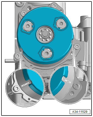
The sensor arm -1- must make contact when attaching the ATF pump -2-.
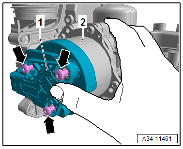
- Tighten the bolts to the specification in the following sequence: -1 through 3-.
- Install the cover -1- for the sensor arm -arrows-.
- Install the Hydraulic Pressure Sensor 1 -G545- and Hydraulic Pressure Sensor 2 -G546-.
Note
- The connectors must not be interchanged.
- Make sure that the connection is correct as shown -1 and 2-.
- Refer to → Chapter "Hydraulic Pressure Sensor 1 -G545- and Hydraulic Pressure Sensor 2 -G546-, Removing and Installing".
- Install the Mechatronic. Refer to → Chapter "Mechatronic, Removing and Installing".
Tightening Specifications:
Refer to → Chapter "Overview - Mechatronic"
Refer to → Chapter "Overview - Valve Body"
Refer to → Chapter "Overview - Transmission Control Module -J217-"
- After working on the DSG Transmission Mechatronic -J743- the function "control module, replacing" must be performed. Refer to Vehicle Diagnostic Tester.
Procedure
- Connect the Vehicle Diagnostic Tester.
- Select Diagnostic mode and start the diagnostic.
- Select the Test plan tab.
- Select individual test button and select the following tree structure one after the other:
- Drivetrain
- 7-Speed Dual Clutch Transmission 0CK/0CL
- 01 - OBD-capable systems
- 02 - Transmission electronics 0CK
- 02 - Transmission electronics, functions
- 02 - Control module, replacing
Valve Body, Removing and Installing
- The same as: Transmission Control Module -J217- removing and installing. Refer to → Chapter "Transmission Control Module -J217-, Removing and Installing".
READ NEXT:
 Hydraulic Pressure Sensor 1 -G545- and Hydraulic Pressure Sensor 2 -G546-,
Removing and Installing
Hydraulic Pressure Sensor 1 -G545- and Hydraulic Pressure Sensor 2 -G546-,
Removing and Installing
Note
The Mechatronic remains installed.
WARNING
The system is under pressure.
The electronic ATF pump must be deactivated every
time before opening the transmission, and the hydrau
Special Tools
Special tools and workshop equipment required
Used Oil Collection and Extraction Unit -SMN372500-
Locking Pin -T10492-
Retaining Strap -T40155-
Oil Sump Assembly Pin -T40199-
Gearbox
SEE MORE:
Battery Charger -VAS5906-
WARNING
Risk of injury. Follow all warning messages and
safety precautions. Refer to
→ Chapter "Warnings and Safety Precautions".
WARNING
Do not check or charge a Battery -A- when the visual
indicator has "no color or is
bright yellow". Jump starting must not be used!
Th
Charging the 12 volt vehicle battery
Fig. 162 Engine compartment: connectors for a charger or
jump start cables
Observe the safety precautions > General
information, in Battery general information.
Requirement: only use chargers with a maximum
charging current of 14.8 volts. The battery cables
remain connected.
The charging cable c
