Audi A4: Hydraulic Pressure Sensor 1 -G545- and Hydraulic Pressure Sensor 2 -G546-, Removing and Installing
 Note
Note
The Mechatronic remains installed.
 WARNING
The system is under pressure.
- The electronic ATF pump must be deactivated every time before opening the transmission, and the hydraulic pressure reservoir is drained.
- Refer to → Chapter "ATF Pump, Deactivating and Draining the Hydraulic Pump Reservoir".
- Remove the transmission fluid pan. Refer to → Chapter "Transmission Fluid Pan, Removing and Installing".
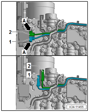
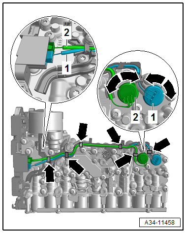
- Release the catches -arrows- from the connector for the Hydraulic Pressure Sensor 1 -G545--1- and Hydraulic Pressure Sensor 2 -G546--2- and disconnect from the Transmission Control Module -J217-.
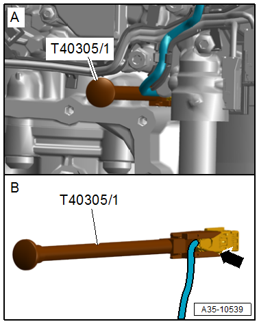
- Using the Assembly Tool -T40305- disconnect the connector for the Gear Position Distance Sensor 2 -G488--arrow- and remove it from the wiring guide.
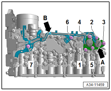
- Loosen the bolts in the sequence -7 to 1-.
- Remove the Hydraulic Pressure Sensor 1 -G545--1- and Hydraulic Pressure Sensor 2 -G546- with the retaining plate -arrow A- and wiring guide -arrow B-.
Installing
Note
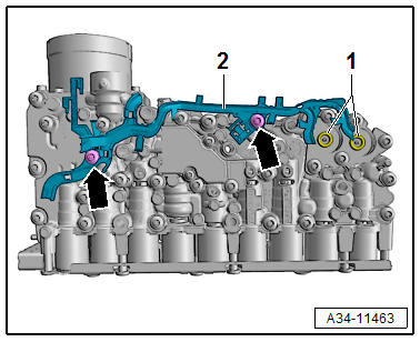
Replace the wiring guide -2-.
- Coat the new seal -1- with ATF and install in the valve body as shown.
- Install the wiring guide -2- with both bolts -arrows- hand-tight.
- Install the Hydraulic Pressure Sensor 1 -G545--1- and Hydraulic Pressure Sensor 2 -G546- with the retaining plate -arrow A- and bolts -1 to 5- hand-tight.
- Clip in the Hydraulic Pressure Sensor 1 -G545--1- and Hydraulic Pressure Sensor 2 -G546- in the wiring guide and engage on the Transmission Control Module -J217-.
Note
- Pay attention that the cable routing is even.
- The cables must not stick out or be kinked.
- Adapt the cable routing by turning the pressure sensors -arrows- as shown.
- Tightening specification and sequence. Refer to → Chapter "Overview - Mechatronic".
- Install the transmission fluid pan. Refer to → Chapter "Transmission Fluid Pan, Removing and Installing".
- After replacing the Hydraulic Pressure Sensor 1 -G545--1- and Hydraulic Pressure Sensor 2 - G546- the calibration of the clutch valve must be performed in the Transmission Control Module -J217-.
Procedure
- Connect the Vehicle Diagnostic Tester.
- Select Diagnostic mode and start the diagnostic.
- Select the Test plan tab.
- Select individual test button and select the following tree structure one after the other:
- Drivetrain
- 7-Speed Dual Clutch Transmission 0CK/0CL
- 01 - OBD-capable systems
- 02 - Transmission electronics 0CK
- 02 - Transmission electronics, functions
- 02 - Basic setting ⇒ clutch valve calibration
Transmission Fluid Auxiliary Hydraulic Pump -V552-, Removing and Installing
Special tools and workshop equipment required
- Locking Pin -T10492-
- Electronic Torque Wrench 3-60Nm -VAS6583-
WARNING
The system is under pressure.
- Deactivate the ATF pump and drain the hydraulic pressure reservoir before removing the transmission fluid pan!
- Refer to → Chapter "ATF Pump, Deactivating and Draining the Hydraulic Pump Reservoir".
 Caution
Contamination damages the Mechatronic.
A clean work environment is required for working on the Mechatronic.
Removing
- Remove the Mechatronic. Refer to → Chapter "Mechatronic, Removing and Installing".
- Remove the Transmission Control Module -J217-. Refer to → Chapter "Transmission Control Module -J217-, Removing and Installing".
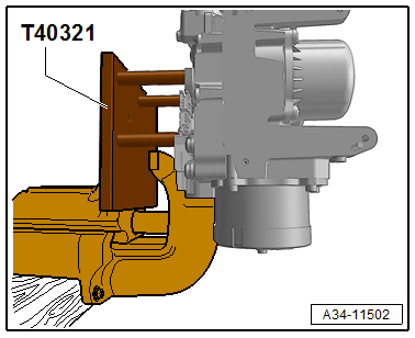
- Secure the Mechatronic on the vise with the Support -T40321- as shown.
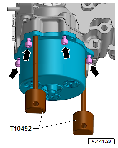
- Remove the bolts -arrows-.
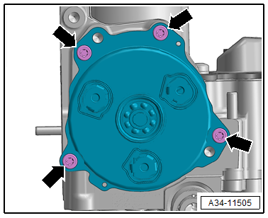
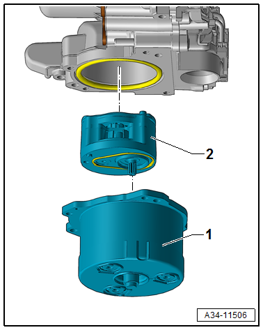
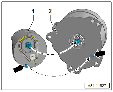
- Remove the ATF motor -1- with the ATF pump -2- downward at the same time pay attention that the ATF pump -2- does not fall down.
Installing
Caution
Contamination damages the Mechatronic.
A clean work environment is required for working on the Mechatronic.
- Place the ATF pump on the ATF motor at the same time pay attention to the correct alignment of the anti-twist mechanism -arrows-.
- Drive the ATF motor and ATF pump using the Locking Pin - T10492- in the valve body.
- Install the bolts evenly all the way and tighten.
Tightening specification.
- Refer to → Chapter "Overview - Valve Body".
- Install the Transmission Control Module -J217-. Refer to → Chapter "Transmission Control Module -J217-, Removing and Installing".
- After replacing the Transmission Fluid Auxiliary Hydraulic Pump -V552- the function "calibrating the fluid auxiliary hydraulic pump" must be performed. Refer to Vehicle Diagnostic Tester.
Procedure
- Connect the Vehicle Diagnostic Tester.
- Select Diagnostic mode and start the diagnostic.
- Select the Test plan tab.
- Select individual test button and select the following tree structure one after the other:
- Drivetrain
- 7-Speed Dual Clutch Transmission 0CK/0CL
- 01 - OBD-capable systems
- 02 - Transmission electronics 0CK
- 02 - Transmission electronics, functions
- 02 - Basic setting ⇒ fluid auxiliary hydraulic pump calibration
- Checking the ATF level. Refer to → 7-Speed Dual Clutch Transmission 0CK; Rep. Gr.34; ATF; ATF Level, Checking.
READ NEXT:
 Special Tools
Special tools and workshop equipment required
Used Oil Collection and Extraction Unit -SMN372500-
Locking Pin -T10492-
Retaining Strap -T40155-
Oil Sump Assembly Pin -T40199-
Gearbox
Transmission Control
Component Location Overview - Transmission Control
1 - DSG Transmission Mechatronic -J743-
2 - Transmission Fluid Temperature Sensor -G93-
3 - Temperature Sensor In Cont
SEE MORE:
Operating
Fig. 4 Driver information system display
Fig. 5 Left side of multifunction steering wheel
Information is organized within various tabs (1) in
the instrument cluster. The tab contents are displayed
in the central area (2).
Requirement: the ignition must be switched on.
Selecting a tab
Press the
Condenser
The condenser conducts heat from compressed refrigerant gas
to the ambient air.
This condenses the refrigerant gas to fluid.
Note
Depending on the version of the refrigerant circuit, the
receiver/dryer is installed (integrated) either on the condenser
or inside the condenser. Refer to
