Audi A4: Service Station, Connecting with No Connection on Low- and High Pressure Side of Refrigerant Circuit
General Information
On the following vehicles, no service connection is provided for the service station on the low-pressure side of the refrigerant circuit; adapters must be used to connect the service station to the refrigerant circuit on these vehicles:
- Audi 80, Audi Cabrio, Audi Coupe
- Audi A4 up to 07.96
- Audi 100/Audi A6 up to 03.97
- Audi A8 up to 11.97
 Note
Note
On vehicles with no or inaccessible connection at compressor, remove A/C Refrigerant Low Pressure Switch -F73- (bridge terminals in connector to A/C Refrigerant Low Pressure Switch -F73-) and screw adapter to this connection. Refer to → Heating, Ventilation and Air Conditioning; Rep. Gr.87; System Overview - Refrigerant Circuit (vehicle-specific repair manual).
Note
- The tools listed below are commercially available or can be obtained from local distributor or importer.
- Should it be necessary to measure the pressures at the switch connections on the high-pressure side, use the adapter Adapter Set for Refrigerant Circuit -VAG1785/9- and proceed in the same manner.
Service Station, Connecting with A/C Adapter Set -VAG1786- to Refrigerant Circuit
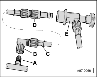
A - Connection with valve (small valve insert) on low-pressure side of refrigerant circuit
B - A/C Adapter Set - Adapter 1 -VAG1786/1-.
C - Commercially available charging hose (short version with 5/8" thread on each end).
D - A/C Adapter Set - Adapter 2 -VAG1786/2- (for connection of quick-release coupling of service station -E-).
Note
- Assemble the adapter and charging hose as shown and connect to connection with valve -A- first.
- The A/C Adapter Set - Adapter 2 -VAG1786/1- is only to be used at connections with "small" valve insert (standard for connection with valve for A/C Refrigerant Low Pressure Switch -F73- and gradually introduced as of 10.94 also at compressor).
- Instead of the A/C Adapter Set - Adapter 1 -VAG1786/1-, the A/C Adapter Set - Adapter 10 -VAG1785/10- can also be used (remove valve from A/C Adapter Set - Adapter 10 -VAG1785/10 -or install valve opener in charging hose).
Service Station, Connecting with A/C Adapter Set - Adapter -VAG1785- to Refrigerant Circuit
- Remove the cap from the connection with valve -A- (at A/C compressor).
- Attach the O-ring -B- to the connection (8.9 mm; 1.8 mm).
- Screw the adapter VAG1785/10 -C- onto the connection -B-.
- Install the valve opener -D- with the appropriate seal in the charging hose connection.
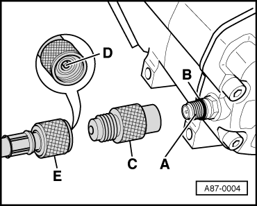
Note
- The type of valve opener -D- and seals required depends on charging hose used (specific to manufacturer).
- The quick-release coupling adapter is not required for connection on the low-pressure side of Audi vehicles.
- Screw the charging hose -E- (to the service station) onto the A/C Adapter Set - Adapter 10 -VAG1785/10-.
Note
To minimize the amount of air and moisture penetrating into the charging hoses and thus into the refrigerant circuit, the charging hoses should be connected together as illustrated.
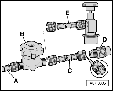
A - Charging hose to service station
B - Hand shut-off valve
C - Charging hose (short version) with valve opener for connection to adapter -D-
D - A/C Adapter Set - Adapter 10 - VAG1785/10-
E - Charging hose (short version) with quick-release coupling adapter (for vehicles with quick-release coupling adapter on low-pressure side).
- Perform the planned tests and measurements.
Servicing Station, Connecting for Measuring and Testing
- Turn off the ignition.
- Connect the service station to the power supply.
- Assemble adapter set and screw to connection on low-pressure side.
- Connect the quick-release coupling adapter to the charging hoses of service station (handwheels not screwed in/hand shut-off valve not open).
- Switch on the service station and evacuate the charging hoses (only necessary if there is air in charging hoses).
- Switch off the service station.
- Remove the cap from the service connection/connection with valve (or remove low-pressure switch and bridge respective electrical connections).
- Connect the service station via the service connections with the quick-release coupling adapters to the vehicle refrigerant circuit.
- Install the handwheel on the quick-release coupling adapters only until valve is definitely open at refrigerant circuit connection (observe pressure gauge, do not strain valve).
- Perform the planned tests and measurements.
READ NEXT:
 General Information
Vehicles with a High Voltage System (Hybrid Vehicles)
Extremely Dangerous Due to High-Voltage
The high-voltage system is under high-voltage. Death or serious
bodily injury by electric shock.
- I
Refrigerant Circuit, Checking Pressure with Service Station
General Information
Note
All test conditions marked * are vehicle-specific and are
described in the Repair Manual for the relevant vehicle.
Check cooling performance.
Connections with val
SEE MORE:
Transmission Fluid Circuit
Overview - Transmission Fluid Circuit
1 - Plug
8 Nm +30º
Replace after removing.
For the ATF check and fill hole
2 - Plug
35 Nm
Replace after removing.
For transmission fluid inspection and fill hole
3 - Transmission Fluid Pump (MTF Pump)
With seal welded
Seat Belt Latch, Function Test
Seat Belt Latch, Checking
- Insert the belt tongue into the seat belt latch until it clicks
into place. Check whether the locking mechanism is properly
engaged by giving the seat belt webbing a firm jerk.
Replace the entire seat belt with the seat belt latch if the
belt tongue fails even o
