Audi A4: Subframe, Lowering
Special tools and workshop equipment required
- Torque Wrench 1331 5-50Nm -VAG1331-
- Torque Wrench 1332 40-200Nm -VAG1332-
- Tensioning Straps -T10038-
- Engine and Gearbox Jack -VAS6931-
- Locating Pins -T40327-
Procedure
 Note
Note
During installation, all cable ties must be installed at the same location.
- Before starting the procedure, determine the curb weight position. Refer to → Chapter "Wheel Bearing in Curb Weight Position, Lifting Vehicles with Coil Spring".
- Secure the subframe. Refer to → Chapter "Subframe, Securing".
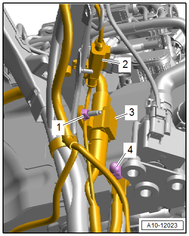
- Disconnect the connector -2- and free up the wire.
- Loosen the nut -1- several turns, and free up and disconnect the connector -3-.
- Remove the nut -4- and free up the ground wire.
- Free up the wires to the steering gear.
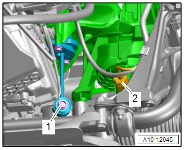
- Equipment versions with electro-hydraulic engine mount: Disconnect the left and right connector -2- for the electrohydraulic engine mount solenoid valve.
- Equipment versions with support bearing: remove the left and right bolt -1- for the support bearing.
Note
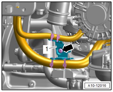
The illustration shows the installation position on a vehicle with a 2.0L TFSI engine.
- Remove the bolt -arrow- and free up the bracket -1- with the wiring harness.
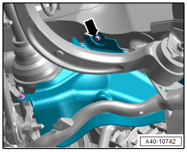
- Remove the left and right bolts -arrow- for the subframe shield.
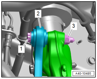
- Remove the left and right nut -3- and the bolt -1- for the coupling rod -2-.
- Remove the steering intermediate shaft from the steering gear and then push together. Refer to → Chapter "Steering Intermediate Shaft, Removing and Installing".
- Remove the left and right drive axle from the transmission. Refer to → Chapter "Drive Axle, Removing and Installing".
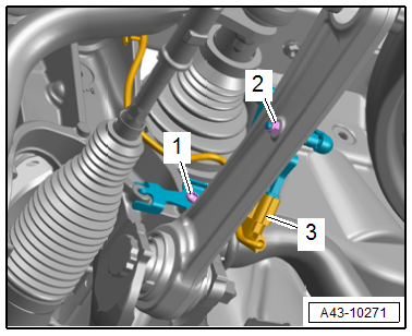
- Equipment versions with electronic damping: Disconnect the left and right connector -3- for the level control system sensor and free up the wire.
Note
Ignore items -1 and 2-.
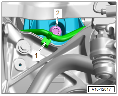
- Equipment versions with SCR system: Free up the SCR delivery line -1- on the subframe.
- Remove the left and right bolt -2- and lower the subframe with the -VAS6931-.
Note
- Make sure there is enough clearance for the wires when lowering the subframe.
- If required for other procedures, tie up the subframe to the body with -T10038- and remove the -VAS6931-.
Installing
Install in reverse order of removal and note the following:
- Remove the -T40327-. Refer to → Chapter "Subframe, Securing".
- Install the steering intermediate shaft. Refer to → Chapter "Steering Intermediate Shaft, Removing and Installing".
Note
Bonded rubber bushings have a limited range of rotation. Only tighten the threaded connections for the suspension when the vehicle is in curb weight position.
- Lift the wheel bearing in the curb weight position. Refer to → Chapter "Wheel Bearing in Curb Weight Position, Lifting Vehicles with Coil Spring"
 WARNING
Risk of accident!
If the vehicle will be driving on the streets, all bolts and nuts must be tightened properly according to the guidelines.
- Connections and wire routing. Refer to → Wiring diagrams, Troubleshooting & Component locations.
Tightening Specifications
- Refer to → Chapter "Overview - Subframe"
- Refer to → Chapter "Overview - Drive Axle"
- Refer to → Body Exterior; Rep. Gr.63; Front Bumper Cover; Overview - Impact Member.
- Refer to → Chapter "Wheels and Tires"
READ NEXT:
 Subframe with Steering Gear, Removing and Installing
Special tools and workshop equipment required
Torque Wrench 1331 5-50Nm -VAG1331-
Torque Wrench 1332 40-200Nm -VAG1332-
Engine and Gearbox Jack -VAS6931-
Ball Joint Splitter -VAS251805-, not illu
Subframe Crossbrace, Removing and Installing
Special tools and workshop equipment required
Torque Wrench 1331 5-50Nm -VAG1331-
Engine and Gearbox Jack -VAS6931-
Puller - Ball Joint -T40043-
Gearbox Support -T40173-
Locating Pin -T40334-
Stabilizer Bar, Removing and Installing
Special tools and workshop equipment required
Torque Wrench 1331 5-50Nm -VAG1331-
Caution
This procedure contains mandatory replaceable parts.
Refer to component overview and parts catalo
SEE MORE:
Child Seat Anchors
Overview - Front Child Seat Anchors
1 - Child Seat Anchor
Front passenger seat only
Bolted to the seat pan
Check after an accident. Refer to
→ Chapter "Child Seat Anchors, Checking After Collision".
Replace damaged or deformed child seat anchor
Removing and installing. Refer
Transmission Control Module -J217-, Removing and Installing
Removing
WARNING
The system is under pressure.
The electronic ATF pump must be deactivated every
time before opening the transmission, and the hydraulic
pressure reservoir is drained.
Refer to
→ Chapter "ATF Pump, Deactivating and Draining the
Hydraulic Pump Reservoir".
