Audi A4: Subframe Crossbrace, Removing and Installing
Special tools and workshop equipment required
- Torque Wrench 1331 5-50Nm -VAG1331-
- Engine and Gearbox Jack -VAS6931-
- Puller - Ball Joint -T40043-
- Gearbox Support -T40173-
- Locating Pin -T40334-
 Caution
This procedure contains mandatory replaceable parts. Refer to component overview and parts catalog prior to starting procedure.
Mandatory Replacement Parts
- Bolts - Subframe Crossbrace to Subframe
- Bolts - Subframe Crossbrace/Steering Gear to Subframe
- Bolt - Clip to Subframe Crossbrace
Removing
 Note
Note
During installation, all cable ties must be installed at the same location.
- Remove the noise insulation. Refer to → Body Exterior; Rep. Gr.66; Noise Insulation; Noise Insulation, Removing and Installing.
- Remove the left and right nuts -arrows- for the subframe shield.
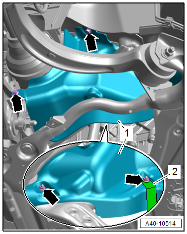
- Equipment version with SCR system: free up the SCR delivery line -1- with the bracket -2- on the crossbrace.
- Free up the wires on the crossbrace.
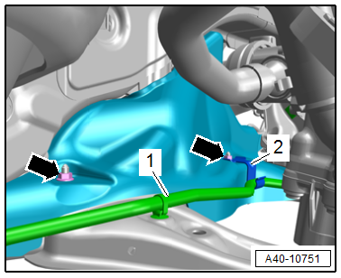
- To protect the threads, remove the nut -arrow- on the left and right from the guide link joint pin just until it is flush with the joint pin threads.
 WARNING
There is a risk of injury from falling components.
When pressing off, the tie rod end loosens abruptly from the wheel bearing housing. Use, for example, the -VAS6931- to secure.
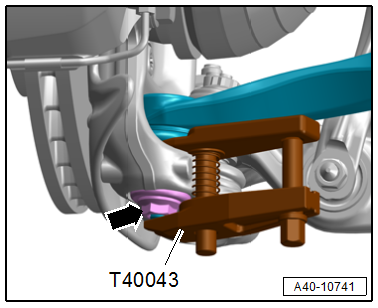
- Press out the guide link joint pin with the -T40043- from the conical seat. Do not damage the CV boot while doing so.
- Remove the nut and free up the guide link on the wheel bearing housing. If necessary, counterhold the joint pin with a TX 40 socket to do this.
- If required, free up the wiring harness and the SCR delivery line.
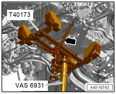
- Support the crossbrace with the -VAS6931- and the -T40173-.
- Secure the crossbrace with the transmission support tensioning strap -arrow-.
Caution
There is a risk of damaging the threads on the subframe threaded connection to the body.
- The subframe bolts on the body must not be loosened or tightened with an impact wrench.
- Always install all bolts by hand for the first few turns.
Note
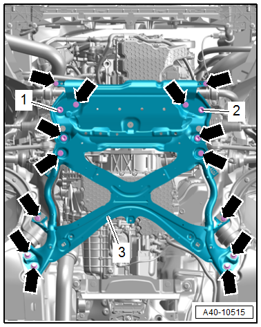
To secure the steering gear, a -T40334- must be screwed in at -1 and 2-.
- Replace bolts -1 and 2- with -T40334- and tighten to 60 Nm.
- The steering gear is now secured.
- Remove the bolts -arrows-, lower the subframe crossbrace -3- using the -VAS6931- and remove it.
Caution
There is a risk of damaging the suspension components.
- If the subframe mount, steering gear or subframe crossbrace are not installed correctly, do not rest the vehicle on its wheels.
- Supporting the vehicle at the subframe or the subframe crossbrace (for example, using a floor jack or similar device) is not permitted.
Installing
Install in reverse order of removal and note the following:
- Bring the crossbrace into the installation position and tighten. Refer to → Fig. "Subframe Crossbrace - Tightening Sequence".
Tightening Specifications
- Refer to → Chapter "Overview - Subframe"
- Refer to → Body Exterior; Rep. Gr.66; Noise Insulation; Overview - Noise Insulation.
Subframe Shield, Removing and Installing
Special tools and workshop equipment required
- Torque Wrench 1410 -VAG1410-
Left Subframe Shield, Removing
- Remove the rear noise insulation. Refer to → Body Exterior; Rep. Gr.66; Noise Insulation; Noise Insulation, Removing and Installing.
- Remove the threaded connections -arrows-.
- If equipped, free up the bracket -2-.
- Remove the shield -1-.
Right Subframe Shield, Removing
- Equipment versions with gasoline engine: remove the front muffler. Refer to → Rep. Gr.26; Exhaust Pipes/Mufflers; Front Muffler, Removing and Installing.
- Equipment versions with TDI engine: Remove the front exhaust pipe with SCR catalytic converter. Refer to → Rep. Gr.26; Exhaust Pipes/Mufflers; Front Exhaust Pipe, Removing and Installing.
- Remove the subframe shield.
Installing
Install in reverse order of removal.
Tightening Specifications
- Refer to → Chapter "Overview - Subframe"
- Refer to → Rep. Gr.26; Exhaust Pipes/Mufflers; Overview - Muffler.
- Refer to → Body Exterior; Rep. Gr.66; Noise Insulation; Overview - Noise Insulation.
READ NEXT:
 Stabilizer Bar, Removing and Installing
Special tools and workshop equipment required
Torque Wrench 1331 5-50Nm -VAG1331-
Caution
This procedure contains mandatory replaceable parts.
Refer to component overview and parts catalo
Overview - Suspension Strut and Upper Control Arm
Overview - Suspension Strut and Upper Control Arm
1 - Bolt
Replace after removing
2 - Control Arm
3 - Shock Absorber Fork
Removing and installing. Refer to
→&nbs
SEE MORE:
Rear Seats
Overview - Bench Seat/Single Seat
1 - Grommets
For securing the rear bench seat
Clipped into the vehicle floor
Replace each time the bench seat is removed
2 - Bench Seat
Removing and installing. Refer to
→ Chapter "Bench Seat/Single Seat, Removing and Installing".
General information
Safety precautions
WARNING
As the driver, you are always completely responsible
for all driving tasks. The assist
systems cannot replace the driver's attention.
Give your full attention to driving the
vehicle, and be ready to intervene in the
traffic situation at all times.
Activate the assi
