Audi A4: Overview - Suspension Strut and Upper Control Arm
Overview - Suspension Strut and Upper Control Arm
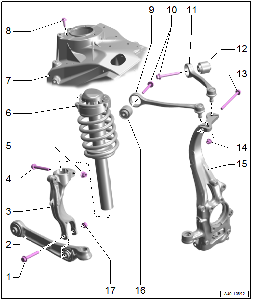
1 - Bolt
- Replace after removing
2 - Control Arm
3 - Shock Absorber Fork
- Removing and installing. Refer to → Chapter "Shock Absorber Fork, Removing and Installing".
4 - Bolt
- Replace after removing
5 - Nut
- 40 Nm
- Replace after removing
6 - Suspension Strut
- Overview. Refer to → Chapter "Overview - Suspension Strut Coil Spring".
7 - Suspension Strut Tower
8 - Bolt
- 20 Nm + 90º
- Replace after removing
9 - Front Upper Control Arm
- Removing and installing. Refer to → Chapter "Upper Control Arm, Removing and Installing".
10 - Bolts
- 50 Nm + 90º
- Replace after removing
- Tighten in the curb weight position. Refer to → Chapter "Wheel Bearing in Curb Weight Position, Lifting Vehicles with Coil Spring".
11 - Rear Upper Control Arm
- Removing and installing. Refer to → Chapter "Upper Control Arm, Removing and Installing".
12 - Bonded Rubber Bushing
- Replacing. Refer to → Chapter "Upper Control Arm Bearing, Replacing".
13 - Bolt
- Replace after removing
14 - Nut
- 40 Nm
- Replace after removing
15 - Wheel Bearing Housing
16 - Bonded Rubber Bushing
- Replacing. Refer to → Chapter "Upper Control Arm Bearing, Replacing".
17 - Nut
- Tightening specification -Item 16-
Overview - Suspension Strut Coil Spring
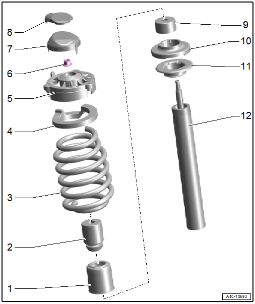
1 - Protective Cover
2 - Stop Buffer
3 - Coil Spring
4 - Spring Support
5 - Strut Mount
- Installation position. Refer to → Fig. "Suspension Strut Coil Spring Installation Position".
6 - Nut
- 50 Nm
- Replace after removing
7 - Cap
- Can only be installed in one position
8 - Cap
- Equipped on some models
9 - Protective Cap
10 - Spring Washer
11 - Lower Spring Plate
12 - Shock Absorber
- Because of different shock absorber valve systems, only install new shock absorbers from the same manufacturer on both axles, if possible.
- Removing and installing. Refer to → Chapter "Suspension Strut, Servicing".
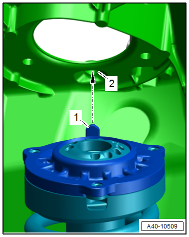
Suspension Strut Coil Spring Installation Position
- The strut mount positioning pin -1- must engage in the hole -2- in the suspension strut tower -arrow-.
Overview - Tower Brace
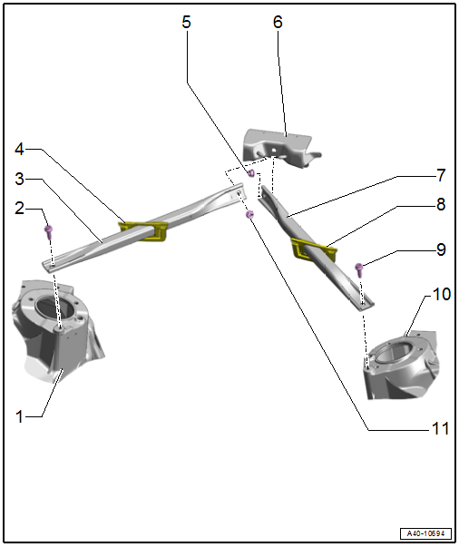
1 - Right Suspension Strut Tower
2 - Bolt
- 20 Nm
3 - Right Tower Brace
- Removing and installing. Refer to → Chapter "Tower Brace, Removing and Installing".
4 - Sealing Piece
5 - Nut
q 20 Nm
6 - Bulkhead
7 - Left Tower Brace
8 - Sealing Piece
9 - Bolt
- 20 Nm
10 - Left Suspension Strut Tower
11 - Nut
- 20 Nm
READ NEXT:
 Suspension Strut, Removing and Installing
Torque Wrench 1331 5-50Nm -VAG1331-
Removing
- Remove the shock absorber fork. Refer to
→ Chapter "Shock Absorber Fork, Removing and Installing".
- Remove the tower brace. Refer t
Upper Control Arm, Removing and Installing
Special tools and workshop equipment required
Vehicle Diagnostic Tester
Torque Wrench 1331 5-50Nm -VAG1331-
Torque Wrench 1331 Insert - Ring Wrench - 16mm -VAG1331/12-,
not illustrated
Torque Wr
Shock Absorber Fork, Removing and Installing
Special tools and workshop equipment required
Spreader Tool -3424-
Torque Wrench 1331 5-50Nm -VAG1331-
Torque Wrench 1332 40-200Nm -VAG1332-
Caution
This procedure contains mandatory rep
SEE MORE:
Settings
Telephone settings
Applies to: vehicles with telephone
Applies to: MMI: Select on the home screen:
PHONE > .
The following options may be possible, depending
on your mobile device:
Decline with text message
Edit voicemail number
Switching between two mobile devices
Requirement: phone 1 an
Audi connect vehicle
control services
Services
Applies to: vehicles with Audi connect vehicle control
Using Audi connect vehicle control services, you
can perform tasks such as viewing data about
your vehicle or control vehicle functions remotely.
You can view and use services available for your
vehicle at my.audi.com or through the my
