Audi A4: Upper Control Arm, Removing and Installing
Special tools and workshop equipment required
- Vehicle Diagnostic Tester
- Torque Wrench 1331 5-50Nm -VAG1331-
- Torque Wrench 1331 Insert - Ring Wrench - 16mm -VAG1331/12-, not illustrated
- Torque Wrench 1332 40-200Nm -VAG1332-
- Engine and Gearbox Jack -VAS6931-
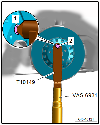
- Engine/Gearbox Jack Adapter - Wheel Hub Support -T10149-
 Caution
This procedure contains mandatory replaceable parts. Refer to component overview and parts catalog prior to starting procedure.
Mandatory Replacement Parts
- Bolt - for Upper Control Arm Bushing
- Bolt/Nut - Upper Control Arm Bushing to Wheel Bearing Housing
Removing
- Before starting the procedure, determine the curb weight position. Refer to → Chapter "Wheel Bearing in Curb Weight Position, Lifting Vehicles with Coil Spring".
- Remove the front wheel. Refer to → Chapter "Wheels and Tires".
- Turn the wheel hub, until a wheel bolt hole is at the top.
- Install the -T10149- with a wheel bolt -2- on the wheel hub.
 Note
Note
Ignore item -1-.
- Support the wheel bearing housing over the -T10149- using the -VAS6931-.
 WARNING
Risk of accident!
- Do not lift or lower the vehicle when the -VAS6931- is under the vehicle.
- Do not leave the -VAS6931- under the vehicle any longer than necessary.
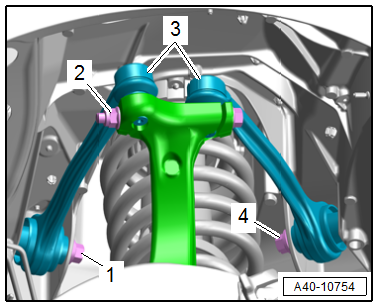
- Loosen the threaded connection -2-.
Caution
There is a risk of damaging the wheel bearing housing.
The slits in the wheel bearing housing must not be widened using a chisel or similar tool!
- Remove the corresponding joint pins in the upper control arm -3- from the wheel bearing housing.
- Remove the bolt -1 or 4- and remove the corresponding upper control arm.
Installing
Install in reverse order of removal and note the following:
- Install the threaded connections for the components with bonded rubber bushings only until the stop, but do not tighten yet.
Note
Bonded rubber bushings have a limited range of rotation. Only tighten the threaded connections for the suspension when the vehicle is in curb weight position.
- Lift the wheel bearing in curb weight position. Refer to → Chapter "Wheel Bearing in Curb Weight Position, Lifting Vehicles with Coil Spring".
Tightening Specifications
- Refer to → Chapter "Overview - Suspension Strut and Upper Control Arm"
- Refer to → Chapter "Wheels and Tires"
Upper Control Arm Bearing, Replacing
Special tools and workshop equipment required
- Subframe Bushing Tool Kit -3301-
- Bearing Installer - Multiple Use -3348-
Caution
This procedure contains mandatory replaceable parts. Refer to component overview and parts catalog prior to starting procedure.
Mandatory Replacement Parts
- Bolt - for Upper Control Arm Bushing
- Bolt/Nut - Upper Control Arm Bushing to Wheel Bearing Housing
Procedure
- The upper control arm is removed. Refer to → Chapter "Upper Control Arm, Removing and Installing"
- Mark the press-in depth of the bonded rubber bushing, for example using a waterproof felt-tip pen.
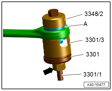
Bonded Rubber Bushing, Pulling Out
- Clamp the control arm in a vise with protective covers.
- Arrange the special tools as shown.
- Remove the bonded rubber bushing -A- by turning the nut -arrow-.
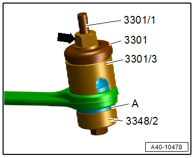
Bonded Rubber Bushing, Installing
Note
Do not use lubricant!
- Transfer the mark for the press-in depth from the old bonded rubber bushing to the new one.
- Arrange the special tools as shown.
- Install the bonded rubber bushing -A- by turning the nut -arrow-, while paying attention to the press-in depth mark made previously.
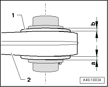
- Check the press-in depth for the bonded rubber bushing -1- inside the control arm -2-.
- Specified value: dimension -a- = dimension -b-.
- When the dimensions are different, tighten the bonded rubber bushings.
READ NEXT:
 Shock Absorber Fork, Removing and Installing
Special tools and workshop equipment required
Spreader Tool -3424-
Torque Wrench 1331 5-50Nm -VAG1331-
Torque Wrench 1332 40-200Nm -VAG1332-
Caution
This procedure contains mandatory rep
Overview - Lower Control Arm and Ball Joint
1 - Wheel Bearing Housing Side Bonded Rubber Bushing
Replacing. Refer to
→ Chapter "Control Arm Ball Bearing, Replacing, Wheel Bearing Housing
Side".
2 - Bolt
Replac
SEE MORE:
Generator
Generator, Checking
Perform Generator Test
Vehicle Diagnostic Tester is attached.
- Select the Diagnostic mode and
start the diagnostics.
- Select the tab Test Plan.
- Select Select Individual Tests
and choose the following sequence.
Body
Electrical Equipment
27 - Starter, volta
General Information - Multifunction Steering Wheel
The button is integrated in the steering wheel for easier
operation of infotainment, telephone and the navigation system.
On Tiptronic, rocker switches are also installed on the left and
right.
The Multifunction Steering Wheel Control Module -J453- (in
the right button) reads out the information
