Audi A4: Overview - Lower Control Arm and Ball Joint
Audi A4 (B9) 2016-2026 Service Manual / Chassis / Front Suspension / Lower Control Arm and Ball Joint / Overview - Lower Control Arm and Ball Joint
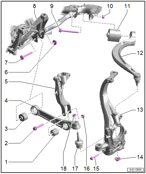
1 - Wheel Bearing Housing Side Bonded Rubber Bushing
- Replacing. Refer to → Chapter "Control Arm Ball Bearing, Replacing, Wheel Bearing Housing Side".
2 - Bolt
- Replace after removing
3 - Subframe Side Bonded Rubber Bushing
- Replacing. Refer to → Chapter "Control Arm Bearing, Replacing, Subframe Side".
4 - Control Arm
- Removing and installing. Refer to → Chapter "Control Arm, Removing and Installing".
5 - Shock Absorber Fork
- Removing and installing. Refer to → Chapter "Shock Absorber Fork, Removing and Installing".
6 - Nut
- 70 Nm + 180º
- Replace after removing
- Tighten in the curb weight position. Refer to → Chapter "Wheel Bearing in Curb Weight Position, Lifting Vehicles with Coil Spring".
7 - Bolt
- Replace after removing
8 - Subframe
9 - Bolt
- Replace after removing
10 - Nut
- 70 Nm + 180º
- Replace after removing
- Tighten in the curb weight position. Refer to → Chapter "Wheel Bearing in Curb Weight Position, Lifting Vehicles with Coil Spring".
11 - Bonded Rubber Bushing
- Replacing. Refer to → Chapter "Guide Link Bonded Rubber Bushing, Removing and Installing".
12 - Guide Link
- Removing and installing. Refer to → Chapter "Guide Link, Removing and Installing".
13 - Wheel Bearing Housing
14 - Nut
- 140 Nm
- Replace after removing
- If reusing the guide link, clean the pin threads of the remaining locking compound residue
15 - Bolt
- 40 Nm
- Replace after removing
16 - Nut
- 90 Nm + 90º
- Replace after removing
- Tighten in the curb weight position. Refer to → Chapter "Wheel Bearing in Curb Weight Position, Lifting Vehicles with Coil Spring".
17 - Ball Joint
- Removing and installing. Refer to → Chapter "Ball Joint, Removing and Installing".
- Contact Surfaces, Inserting in Wheel Bearing Housing.
18 - Nut
- 140 Nm
- Replace after removing
- If reusing the ball joint, clean the pin threads from of remaining locking compound residue
READ NEXT:
 Control Arm, Removing and Installing
Special tools and workshop equipment required
Spreader Tool -3424-
Torque Wrench 1332 40-200Nm -VAG1332-
Engine and Gearbox Jack -VAS6931-
Ball Joint Splitter -VAS251805-
Engine/Gearbox Jack Ada
Guide Link, Removing and Installing
Special tools and workshop equipment required
Torque Wrench 1332 40-200Nm -VAG1332-
Torque Wrench 1332 Insert - Ring Wrench - 21mm -VAG1332/7-
Engine and Gearbox Jack -VAS6931-
Puller - Ball Join
Control Arm Ball Bearing, Replacing
Control Arm Ball Bearing, Replacing, Wheel Bearing Housing Side
Special tools and workshop equipment required
Press Plate -VW402-
Press Piece - Multiple Use -VW412-
Press Piece - 42mm -VW516-
Pre
SEE MORE:
Seat Belts
Component Location Overview - Seat Belts and Mounting Points
Note
The Avant is shown.
1 - Front Belt End Fitting
Overview. Refer to
→ Chapter "Overview - Front Three-Point Seat Belt".
2 - Automatic Belt Retractor
For the front three-point seat belt
With:
Rear Lid Lower Trim Panel, Removing and Installing
Lower Rear Lid Trim Panel, Removing and Installing, Sedan
Special tools and workshop equipment required
Pry Lever -80-200-
Trim Removal Wedge -3409-
Removal Wedge -T40233-
Omega Clip Tool -T40280-
Removing
- Remove the rear lid latch trim panel -1-
using the -T40233- in the direction of
© 2019-2026 Copyright www.audia4b9.com
