
Audi A4: Control Arm Ball Bearing, Replacing
Control Arm Ball Bearing, Replacing, Wheel Bearing Housing Side
Special tools and workshop equipment required
- Press Plate -VW402-
- Press Piece - Multiple Use -VW412-
- Press Piece - 42mm -VW516-
- Press Piece - Reverse Gear Syncro -3296-
- Assembly Paste -G 052 109 A2-
 Caution
This procedure contains mandatory replaceable parts. Refer to component overview and parts catalog prior to starting procedure.
Mandatory Replacement Parts
- Bolt/Nut - Control Arm to Subframe
- Bolt - Control Arm to Shock Absorber Fork
- Nut - Ball Joint to Control Arm
Procedure
- The control arm is removed. Refer to → Chapter "Control Arm, Removing and Installing".
Bonded Rubber Bushing, Pressing Out
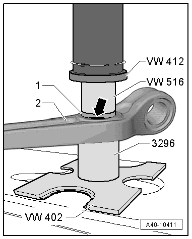
- Mark the press-in depth of the bonded rubber bushing -1- for example using a waterproof felt-tip pen -arrow-.
- Arrange the special tools as shown.
 Note
Note
Hold the control arm firmly in position while pressing the bonded rubber bushing out and in.
- Press out the bonded rubber bushing from the control arm -2-.
Bonded Rubber Bushing, Pressing In
- Transfer the press-in depth mark from the old bonded rubber bushing to the new one.
- Thinly coat the bonded rubber bushing with Assembly Paste -G 052 109 A2-.
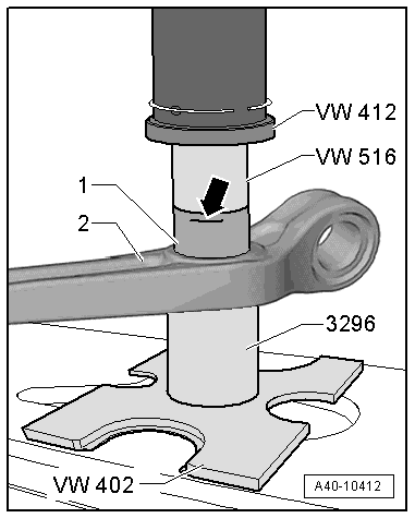
- Insert the bonded rubber bushing -1- in the control arm -2-.
- Arrange the special tools as shown.
- Press the bonded rubber bushing in the control arm, and do not tilt it.
- Pay attention to the mark -arrow- for the press-in depth.
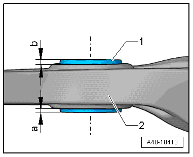
- Check the press-in depth of the bonded rubber bushing -1- in the control arm -2-.
- Specified value: dimension -a- = dimension -b-.
- If the values are different, press in the bonded rubber bushing again.
Control Arm Bearing, Replacing, Subframe Side
Special tools and workshop equipment required
- Press Plate -VW402-
- Press Piece - Multiple Use -VW412-
- Press Piece - Reverse Gear Syncro -3296-
- Puller - Differential Bearing -T40032-
- Assembly Paste -G 052 109 A2-
Caution
This procedure contains mandatory replaceable parts. Refer to component overview and parts catalog prior to starting procedure.
Mandatory Replacement Parts
- Bolt/Nut - Control Arm to Subframe
- Bolt - Control Arm to Shock Absorber Fork
- Nut - Ball Joint to Control Arm
Procedure
- The control arm is removed. Refer to → Chapter "Control Arm, Removing and Installing".
Bonded Rubber Bushing, Pressing Out
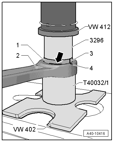
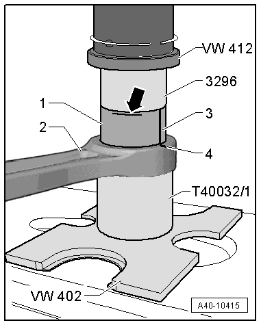
- Mark the press-in depth -arrow- and the installation position -3 and 4- on the bonded rubber bushing -1- as shown using, for example, a waterproof felt-tip pen.
- Arrange the special tools as shown.
Note
Hold the control arm firmly in position while pressing the bonded rubber bushing out and in.
- Press out the bonded rubber bushing from the control arm -2-.
Bonded Rubber Bushing, Pressing In
- Transfer the press-in depth mark from the old bonded rubber bushing to the new one.
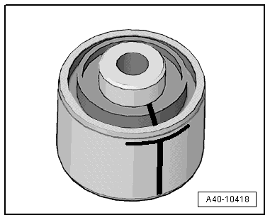
- Thinly coat the bonded rubber bushing with Assembly Paste -G 052 109 A2-.
- Insert the bonded rubber bushing -1- in the control arm -2- and align to the mark -3 to 4-.
- Arrange the special tools as shown.
- Press the bonded rubber bushing in the control arm, and do not tilt it.
- Pay close attention to the press-in depth mark -arrow-.
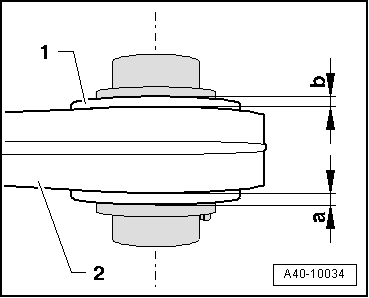
- Check the press-in depth of the bonded rubber bushing -1- in the control arm -2-.
- Specified value: dimension -a- = dimension -b-.
- If the values are different, press in the bonded rubber bushing again.
READ NEXT:
 Ball Joint, Removing and Installing
Special tools and workshop equipment required
Torque Wrench 1332 40-200Nm -VAG1332-
Torque Wrench 1332 Insert - Ring Wrench - 21mm -VAG1332/7-
Ball Joint Splitter -T40277-
Caution
This p
Overview - Wheel Bearing
1 - Wheel Bearing Housing
Removing and installing. Refer to
→ Chapter "Wheel Bearing Housing, Removing and Installing".
2 - Bolt
80 Nm + 90º
Replace after removing
SEE MORE:
Cruise control system
Description
Applies to: vehicles with cruise control system
The cruise control system assists the driver in
maintaining a constant speed above approximately
15 mph (20 km/h). The system maintains
the desired speed by braking and accelerating.
WARNING
Observe the safety precautions and note the
Transmission, Transporting
Special tools and workshop equipment required
Shop Crane -VAS6100-
Lifting Tackle -3033-
Hook And Support Tool -3311- with Hook And Support Tool -
Bolt -3311/1-
Retaining Strap -T40155-
Caution
Risk of damaging the transmission by mixing ATF and
transmission fluid (MTF) through the
