Audi A4: Wheel Housing Liner
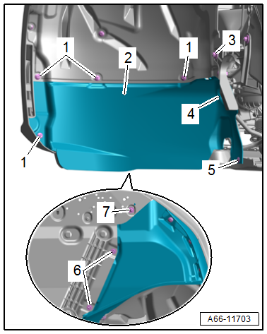
Overview - Front Wheel Housing Liner
Overview - Wheel Housing Liner
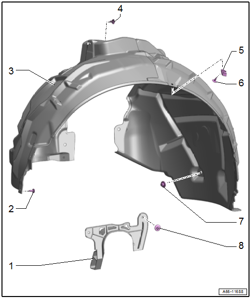
1 - Drive Axle Cover
- Removing and installing. Refer to → Chapter "Drive Axle Cover, Removing and Installing".
2 - Bolt
- 2 Nm
- Quantity: 6
3 - Front Wheel Housing Liner
- Removing and installing. Refer to → Chapter "Front Wheel Housing Liner, Removing and Installing".
4 - Christmas Tree Clip
5 - Bracket
- For the wheel housing liner to the fender
6 - Bolt
- 2 Nm
7 - Nut
- 2 Nm
- Quantity: 5
8 - Nut
- 2 Nm
- Quantity: 2
Overview - Wheel Spoiler
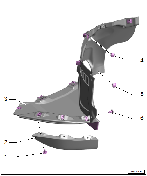
1 - Bolt
- 2 Nm
- Quantity: 3
2 - Spoiler Lip
3 - Front Wheel Spoiler
- Removing and installing. Refer to → Chapter "Front Wheel Spoiler, Removing and Installing".
4 - Christmas Tree Clip
5 - Expanding Rivet
6 - Bolt
- 2 Nm
Overview - Rear Wheel Housing Liner
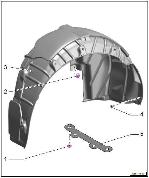
1 - Nut
- 2 Nm
- Quantity: 4
2 - Nut
q 2 Nm
- Quantity: 9
3 - Rear Wheel Housing Liner
- Removing and installing. Refer to → Chapter "Rear Wheel Housing Liner, Removing and Installing".
4 - Bolt
- 2 Nm
- Quantity: 4
5 - Spoiler
- For the spare tire well
- Removing and installing. Refer to → Chapter "Spare Tire Well Spoiler, Removing and Installing".
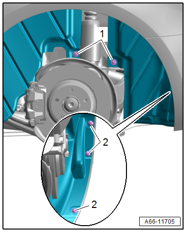
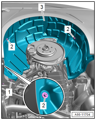
Front Wheel Housing Liner, Removing and Installing
Removing
- Remove the drive axle cover. Refer to → Chapter "Drive Axle Cover, Removing and Installing".
- Remove the Christmas tree clip -3-.
- Remove the bolt -4- and then disengage the bracket from the fender.
- Remove the nut -2- and bolts -1-.
- Remove the wheel housing liner -5-.
Installing
Install in reverse order of removal.
Tightening Specifications
- Refer to → Chapter "Overview - Front Wheel Housing Liner"
Front Wheel Spoiler, Removing and Installing
Removing
- Remove the bolts -1 and 7-.
- Remove the expanding rivet -5- and Christmas tree clip -4-.
- Remove the front nut -3- for the drive axle cover.
- Loosen the quick release -6- and remove the wheel spoiler -2-.
- Free up the breather hose for the headlamp.
Installing
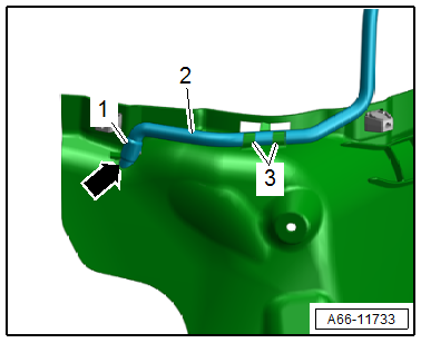
Install in reverse order of removal and note the following:
- Insert the breather hose -2- into the hole -arrow- up to the bulge -1-.
- Insert the breather hose in the mount -3- to secure it.
Tightening Specifications
- Refer to → Chapter "Overview - Front Wheel Housing Liner"
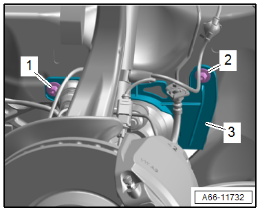
Drive Axle Cover, Removing and Installing
Removing
- Push the front wheel to the left.
- Remove the nut -1-.
- Push the front wheel to the right.
- Remove the nut -2-.
- Pull the drive axle cover -3- off the threaded pins and remove it downward toward the rear.
Installing
Install in reverse order of removal.
Tightening Specifications
- Refer to → Chapter "Overview - Front Wheel Housing Liner"
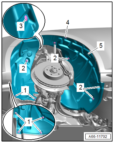
Rear Wheel Housing Liner, Removing and Installing
Removing
- Rear wheel removed. Refer to → Suspension, Wheels, Steering; Rep. Gr.44; Wheels, Tires.
- Remove the nuts -arrows-.
- Remove the nuts -1- and bolts -2-.
- Remove the nuts -2- and the bolt -1-.
- Remove the wheel housing liner -3-.
Installing
Install in reverse order of removal.
Tightening Specifications
- Refer to → Chapter "Overview - Rear Wheel Housing Liner"
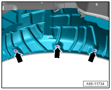
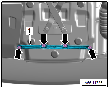
Spare Tire Well Spoiler, Removing and Installing
Removing
- Remove the nuts -arrows-.
- Remove the spoiler -1-.
Installing
Install in reverse order of removal.
Tightening Specifications
- Refer to → Chapter "Overview - Rear Wheel Housing Liner"
READ NEXT:
 Name Badges and Emblems
Overview - Name Badges and Emblems
1 -
Emblem
Removing and installing. Refer to
→ Chapter "Radiator Grille Name Badges and Emblems, Removing and
Installing".
2 -
quat
Trailer Hitch
Overview - Trailer Hitch
1 -
Information Label
On the left side of the body at the rear
2 -
Towing Recognition Control Module -J345-
Removing and installing. Refer to
→&nb
SEE MORE:
Input Shaft Double Shaft Seal, Replacing
Special tools and workshop equipment required
Puller - Crankshaft/Power Steering Seal -T20143-
Thrust Piece -T40300-
Clutch, engaging bearing and slave cylinder removed. Refer
to
→ Chapter "Dual Clutch, Removing and Installing".
- With the Puller - Crankshaft/Power Steering Seal
Door, Removing and Installing
Removing
- Disconnect the door cut-off connector -1-
at the B-pillar. Refer to
→ Electrical Equipment; Rep. Gr.97; Connectors.
- Tape off the B-pillar in the door arrester area using adhesive
tape, so that the paint will not be damaged.
- Remove the door arrester b
