Audi A4: Trailer Hitch
Overview - Trailer Hitch
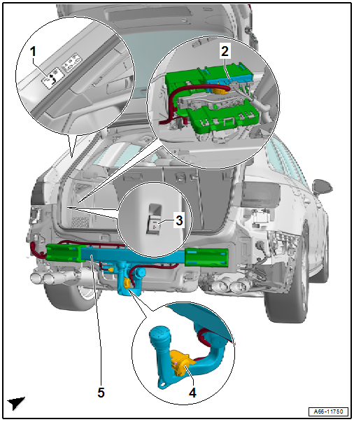
1 - Information Label
- On the left side of the body at the rear
2 - Towing Recognition Control Module -J345-
- Removing and installing. Refer to → Chapter "Towing Recognition Control Module -J345-, Removing and Installing".
3 - Trailer Hitch Release Button -E754-
- Removing and installing. Refer to → Electrical Equipment; Rep. Gr.96; Controls; Component Location Overview - Luggage Compartment Controls.
4 - Trailer Socket -U10-
- Removing and installing. Refer to → Electrical Equipment General Information; Rep. Gr.96; Trailer Hitch.
5 - Trailer Hitch
- Only removable with the impact member
- Removing and installing. Refer to → Chapter "Overview - Impact Member".
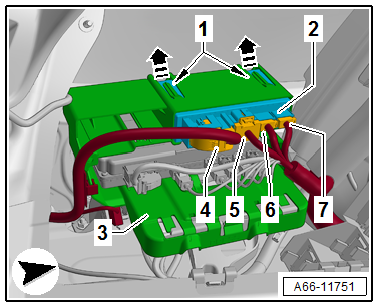
Towing Recognition Control Module -J345-, Removing and Installing
Removing
- Open the left service cover. Refer to → Body Interior; Rep. Gr.70; Luggage Compartment Trim Panels; Overview - Luggage Compartment Side Trim Panel.
- Disconnect the connectors -4 through 7-.
- Release the retainers -1- in the direction of -arrows- and remove the Towing Recognition Control Module -J345--2- from the bracket -3-.
Installing
Install in reverse order of removal.
Special Tools
Special tools and workshop equipment required
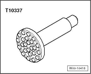
- Engine/Gearbox Jack - Gearbox Support -T10337-
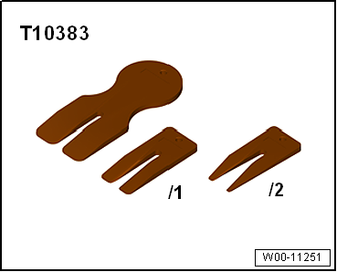
- Wedge Set -T10383-
- Wedge 1 -T10383/1-
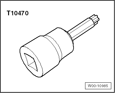
- Socket - Torx T50 -T10470-
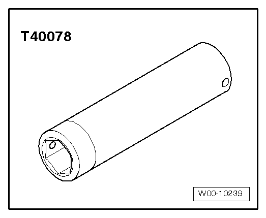
- Body Socket -T40078-
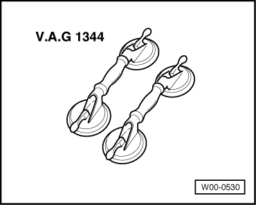
- Double Suction Lifter -VAG1344-
- Wiring Harness Repair Set - Hot Air Blower -VAS1978/14A-
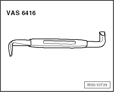
- Angled Screwdriver -VAS6416-
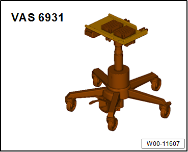
- Engine and Gearbox Jack -VAS6931-
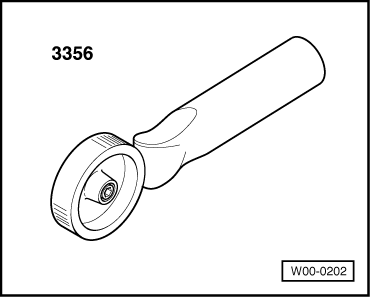
- Roller -3356-
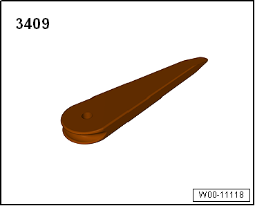
- Trim Removal Wedge -3409-
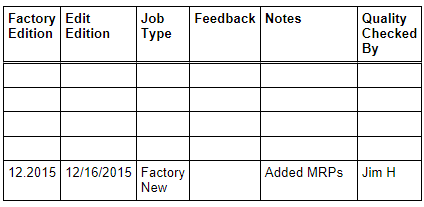
Revision History
DRUCK NUMBER: A005A014621
READ NEXT:
 Safety Precautions
Safety Precautions when Working on Vehicles with Start/Stop System
There is a risk of injury due to the engine starting
unexpectedly.
The engine can start unexpectedly on vehicles with an activated
SEE MORE:
Driver Side Instrument Panel Cover, Removing and Installing
Removing
- Remove the driver side instrument panel side cover. Refer to
→ Chapter "Instrument Panel Side Cover, Removing and Installing".
- Equipped on some models: Open the storage compartment cover
-1- and remove the screws
-arrows B-.
- Remove the screws -arrows A-.
- U
Right and Left Multifunction Buttons on Steering Wheel -E441-/-E440-,
Removing and Installing
Right and Left Multifunction Buttons on Steering Wheel -E441-/-E440-,
Removing and Installing, Steering Wheel with Round Airbag
Special tools and workshop equipment required
Trim Removal Wedge -3409-
The multifunction buttons -2-
are clipped to the decorative trim -1-.
The decorative trim -1-
© 2019-2026 Copyright www.audia4b9.com
