Audi A4: Transmission, Disassembling and Assembling
 WARNING
The system is under pressure.
- The electronic ATF pump must be deactivated every time before opening the transmission, and the hydraulic pressure reservoir is drained.
- Refer to → Chapter "ATF Pump, Deactivating and Draining the Hydraulic Pump Reservoir".
FWD Vehicles
Special tools and workshop equipment required
- Press Tool -T40323-
- Assembly Tool -T40305-
- Slide Hammer Set -VW771-
- Gearbox Assembly Tool -T40213 /1/2/3-
- Retaining Strap -T40155-
- Shop Crane -VAS6100-
- Puller - Grease Cap -VW637/2-
- Wiring Harness Repair Set - Hot Air Blower -VAS1978/14A-
 Caution
Risk of damaging the transmission by mixing ATF and transmission fluid (MTF) through the same bleeder.
The ATF and transmission fluid must be drained.
Removing
- Draining the ATF. Refer to → Rep. Gr.34; ATF, Draining and Filling.
- Draining the transmission fluid. Refer to → Rep. Gr.34; Transmission Fluid, Draining and Filling.
- Remove the clutch. Refer to → Chapter "Dual Clutch, Removing and Installing".
- Remove the transmission fluid pan. Refer to → Chapter "Transmission Fluid Pan, Removing and Installing".
- Turn the transmission on the Gearbox Support -T40206- 180º.
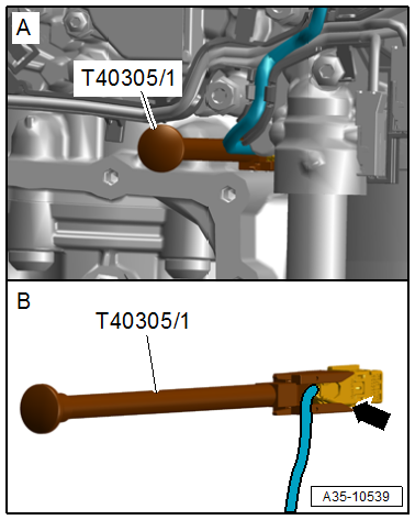
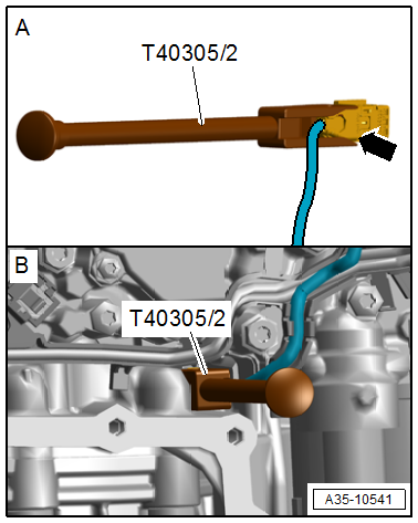
- Disconnect the connector -arrow- using the Assembly Tool -T40305-.
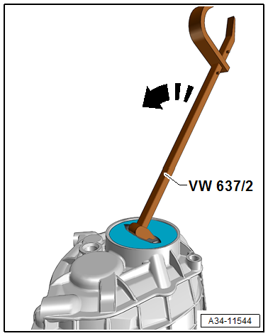
- Remove the end cover to do so chisel the center of the cover and remove using the Puller - Grease Cap -VW637/2- as shown.
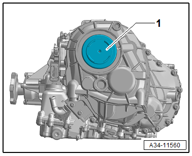
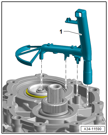
- Remove the oil catch tray -1-.
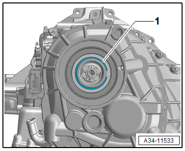
- Remove the circlip -1-.
- Remove the bolts -1 to 6-.
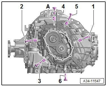
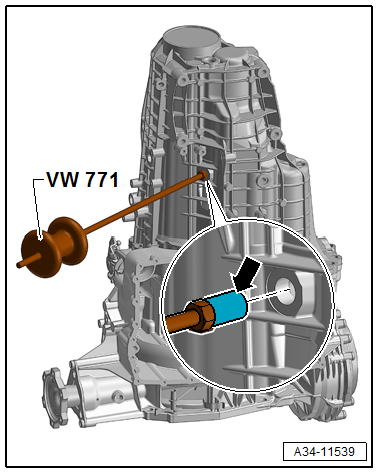
- Remove the centering bushing -arrows- with the Slide Hammer Set -VW771-.
 Note
Note
Bolt -6- without centering bushing.
- Remove the bolts for the transmission housing.
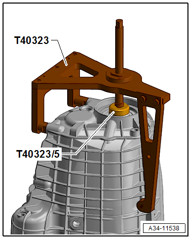
- Remove the transmission housing with the Press Tool -T40323-.
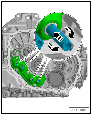
- Prepare the 1/4 inch tool with Torx T30 and flexible extension as shown.
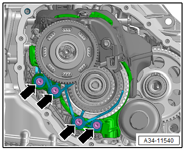
- Remove the bolts for the gear positioner -arrows-.
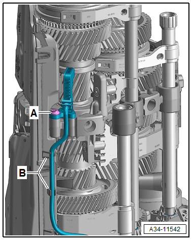
- Remove the bolt for the Transmission Input Speed Sensor 1 -G632--arrow A- and remove the line from the oil pan -arrow B-.
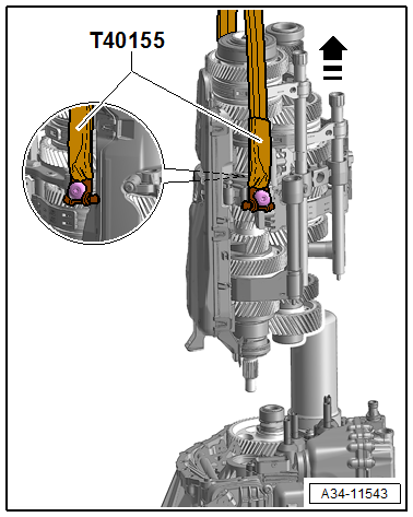
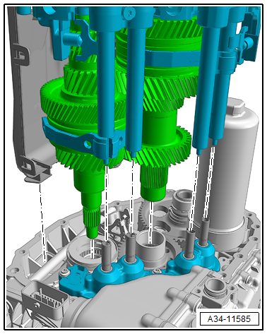
- Secure the Retaining Strap -T40155- on the gear set as shown and slowly and carefully remove with the Shop Crane -VAS6100- from the transmission housing.
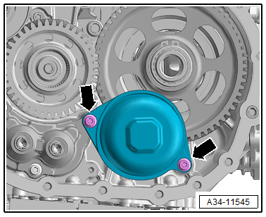
- Loosen the bolts -arrow- for the hydraulic pressure reservoir but do not remove.
Note
- If the hydraulic pressure reservoir lifts when loosening the bolts the ATF system is still under pressure.
- In this case the bolts from the Mechatronic must be minimally loosened to reduce the pressure in the ATF system via the sealing surfaces.
- Refer to → Chapter "ATF Pump, Deactivating and Draining the Hydraulic Pump Reservoir".
- Remove the bolts -arrows- and the hydraulic pressure reservoir.
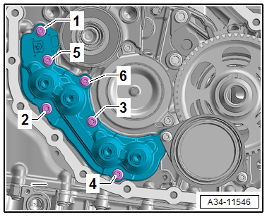
- Remove the bolts -1 through 6- and remove the gear positioner module.
Installing
- Insert the gear positioner module and tighten the bolts in the sequence -1 to 6- hand-tight.
- Install the hydraulic pressure reservoir with new seals and tighten the bolts -arrow- hand-tight evenly.
- Tighten the gear positioner and pressure reservoir to the tightening specification. Refer to → Fig. "Gear Positioner and Pressure Reservoir Tightening Sequence".
- Bring the gear positioner into the basic setting.
- Push the gear positioner by hand and turn at the same time it until it engages and determine the current backlash.
- Carefully remove the gear set.
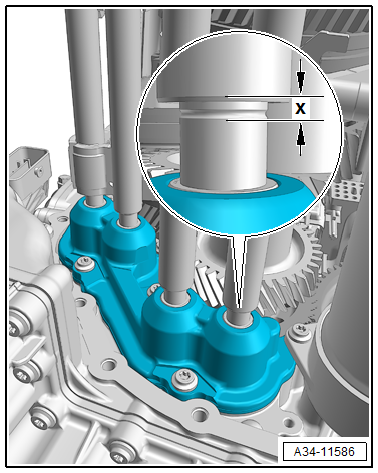
- Guide together the bearing area and gear positioner -arrows- evenly.
- Install the gear positioner -arrows- hand-tight.
- When the gear positioner is installed correctly the dimension -X- is approximately 2 mm.
- Tighten the bolts for the gear positioner to the tightening specification. Refer to → Chapter "Overview - Gear Set, FWD Vehicles".
- Tighten the bolt -A- for the Transmission Input Speed Sensor 1 -G632- and install the line in the oil pan.
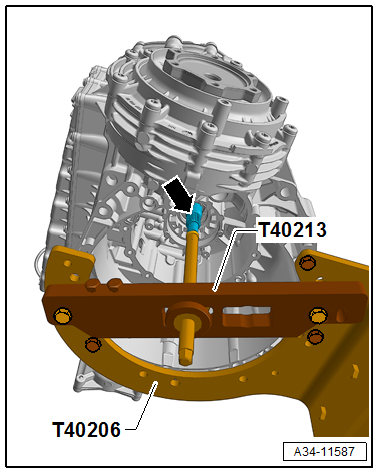
- Install the Gearbox Assembly Tool -T40213A- on the transmission.
Note
This step is necessity to that the bearing "E" in the transmission housing can be mounted correctly on the shaft.
- Install the spindle from the Gearbox Assembly Tool -T40213A- by hand until the input shaft has raised approximately 2 to 3 mm and there is a small resistance when turning.
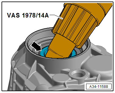
- Position the new seal and check if both centering pins are installed.
- Warm the inner race of the bearing "E"-arrow- with the Wiring Harness Repair Set - Hot Air Blower -VAS1978/14A- to a maximum of 100 ºC (212 ºF).
Caution
Risk of damaging the bearing seal.
Only warm up the inner bearing race.
- Guide together the transmission housing and the transmission.
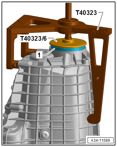
- Install the new circlip -1- for the bearing "E".
Note
- The circlip had different installed dimensions.
- If the bearing "E" is not replaced, a circlip with the same dimension as the old circlip must be installed.
- For a new bearing "E" the largest possible circlip to be installed must be used.
- Remove the Gearbox Assembly Tool -T40213A- from the transmission.
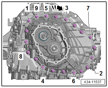
- Tighten the transmission housing with new bolts. Tightening sequence and tightening specification. Refer to → Chapter "Overview - Transmission, FWD Vehicles".
- Tighten the bolts for the transmission housing to the tightening sequence. Refer to → Fig. "Transmission Housing Tightening Specification and Sequence.".
- Push in the centering bracket -A- for the gear set all the way.
Note
Bolt -6- without centering bracket.
- Tighten the new bolts for the gear set -1 to 6- with the tightening sequence. Refer to → Fig. "Wheel Set Tightening Specification and Sequence.".
- Install the oil catch tray -1-.
- Press in the new end cover with the Press Tool -T40323-.
Caution
Oil loss due to improper assembly.
- The end cover is installed "dry" in the cleaned housing, never use locking agent.
- Let the end cover be tensioned 10 minutes with the Press Tool -T40323-.
- Install the connector with the Assembly Tool -T40305-.
- Install the clutch. Refer to → Chapter "Dual Clutch, Removing and Installing".
- Install the transmission fluid pan. Refer to → Chapter "Transmission Fluid Pan, Removing and Installing".
- Fill the ATF. Refer to → Rep. Gr.34; ATF; ATF, Draining and Filling.
- Fill the transmission fluid. Refer to → Rep. Gr.34; Transmission Fluid; Transmission Fluid, Draining and Filling.
AWD Vehicles
Special tools and workshop equipment required
- Press Tool -T40323-
- Slide Hammer Set -VW771-
- Gearbox Assembly Tool -T40213 /1/2/3-
- Retaining Strap -T40155-
- Shop Crane -VAS6100-
- Wiring Harness Repair Set - Hot Air Blower -VAS1978/14A-
Caution
Risk of damaging the transmission by mixing ATF and transmission fluid (MTF) through the same bleeder.
The ATF and transmission fluid must be drained.
Removing
- Draining the ATF. Refer to → Rep. Gr.34; ATF, Draining and Filling.
- Draining the transmission fluid. Refer to → Rep. Gr.34; Transmission Fluid, Draining and Filling.
- Remove the clutch. Refer to → Chapter "Dual Clutch, Removing and Installing".
- Turn the transmission on the Gearbox Support -T40206- 180º.
- Remove the differential.
- Remove the oil catch tray -1-.
- Remove the circlip -1-.
- Remove the bolts for the transmission housing.
- Remove the bolts -1 to 6-.
- Remove the centering bushing -arrows- with the Slide Hammer Set -VW771-.
Note
Bolt -6- without centering bushing.
- Remove the transmission housing with the Press Tool -T40323-.
- Prepare the 1/4 inch tool with Torx T30 and flexible extension as shown.
- Remove the bolts for the gear positioner -arrows-.
- Remove the bolt for the Transmission Input Speed Sensor 1 -G632--A- and remove the line from the oil pan -B-.
- Secure the Retaining Strap -T40155- on the gear set as shown and slowly and carefully remove with the Shop Crane -VAS6100- from the transmission housing.
- Pay attention to both needle bearings -arrows-.
- Loosen the bolts -arrow- for the hydraulic pressure reservoir but do not remove.
Note
- If the hydraulic pressure reservoir lifts when loosening the bolts the ATF system is still under pressure.
- In this case the bolts from the Mechatronic must be minimally loosened to reduce the pressure in the ATF system via the sealing surfaces.
- Refer to → Chapter "ATF Pump, Deactivating and Draining the Hydraulic Pump Reservoir".
- Remove the bolts -arrows- and the hydraulic pressure reservoir.
- Remove the bolts -1 through 6- and remove the gear positioner module.
Installing
- Insert the gear positioner module and tighten the bolts in the sequence -1 to 6- hand-tight.
- Install the hydraulic pressure reservoir with new seals and tighten the bolts -arrow- hand-tight evenly.
- Tighten the gear positioner and pressure reservoir to the tightening specification. Refer to → Chapter "Overview - Gear Set, FWD Vehicles".
- Bring the gear positioner into the basic setting.
- Push the gear positioner by hand and turn at the same time it until it engages and determine the current backlash.
- Install the needle bearing -arrow-.
- Carefully remove the gear set.
- Guide together the bearing area and gear positioner -arrows- evenly.
- Install the needle bearing -arrow-.
- Install the gear positioner -arrows- hand-tight.
- When the gear positioner is installed correctly the dimension x must be approximately 2 mm.
- Tighten the bolts for the gear positioner to the tightening specification.
- Tighten the bolt -A- for the Transmission Input Speed Sensor 1 -G632- and install the line -B- in the oil pan.
- Install the Gearbox Assembly Tool -T40213A- on the transmission.
Note
This step is necessity to that the bearing "E" in the transmission housing can be mounted correctly on the shaft.
- Install the spindle from the Gearbox Assembly Tool -T40213A- by hand only until the input shaft has raised 2 to 3 mm.
- Position the new seal and check if both centering pins are installed.
- Warm the inner race of the bearing "E"-arrow- with the Wiring Harness Repair Set - Hot Air Blower -VAS1978/14A- to a maximum of 100 ºC (212 ºF).
- Guide together the transmission housing and the transmission.
- Install the new circlip -1- for the bearing "E".
Note
- The circlip had different installed dimensions.
- If the bearing "E" is not replaced, a circlip with the same dimension as the old circlip must be installed.
- For a new bearing "E" the largest possible circlip to be installed must be used.
- Remove the Gearbox Assembly Tool -T40213A- from the transmission.
- Install the oil catch tray -1-.
- Tighten the transmission housing with new bolts. Tightening sequence and tightening specification. Refer to → Chapter "Overview - Transmission, FWD Vehicles".
- Press in the new end cover with the Press Tool -T40323-.
Caution
Oil loss due to improper assembly.
- The end cover is installed "dry" in the cleaned housing, never use locking agent.
- Let the end cover be tensioned 10 minutes with the Press Tool -T40323-.
- Install the connector with the Assembly Tool -T40305-.
- Install the clutch. Refer to → Chapter "Dual Clutch, Removing and Installing".
- Install the transmission fluid pan. Refer to → Chapter "Transmission Fluid Pan, Removing and Installing".
Hydraulic Pressure Reservoir, Disposing
Note
- The installed hydraulic pressure reservoir is around a closed hollow body; that is impinged on by the prefilled working gas (nitrogen) with an inner pressure
- Because it is prohibited to scrap a closed hollow body, the hydraulic pressure reservoir must be drained before disposal.
- Remove the hydraulic pressure reservoir. Refer to → Chapter "Transmission, Disassembling and Assembling".
WARNING
The system is under pressure.
- Wear protective eyewear and hearing protection when engaging the pressure reservoir.
- When the drill bit passes through in the gas space due to the internal pressure the shavings can be flung around.
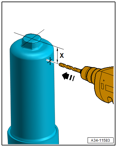
- Tension the hydraulic pressure reservoir in the vise.
- Completely drill out approximately 25 mm -dimension x- from the square deck area with a 3 mm drill bit.
- The pressureless hydraulic pressure reservoir can then be scrapped.
READ NEXT:
 Transmission Fluid Circuit
Overview - Transmission Fluid Circuit
1 - Plug
8 Nm +30º
Replace after removing.
For the ATF check and fill hole
2 - Plug
35 Nm
Replace after removing.
For transmission
DSG Transmission Mechatronic -J743-
Overview - Mechatronic
1 - Transmission Fluid Pan
Removing and installing. Refer to
→ Chapter "Transmission Fluid Pan, Removing and Installing".
2 - Bolt
Tightenin
Transmission Fluid Pan, Removing and Installing
Special tools and workshop equipment required
Engine Bung Set -VAS6122-
Used Oil Collection and Extraction Unit -SMN372500-
Removing
Note
General repair instructions. Refer to
→
SEE MORE:
CV Joint, Servicing
Outer CV Joint, Removing
- Clamp the drive axle in a vise with protective covers.
- Open both clamps and remove the CV boot from the outer
joint.
- Drive out the CV joint from the drive axle with a copper or
brass mandrel -A- on the inner
ring.
- Remove joint and CV boot.
Out
A/C Pressure Switch -F129-
Note
Switch pressures, removing and installing switches as well
as switch arrangement and version. Refer to vehicle specific
refrigerant circuit
→ Heating, Ventilation and Air Conditioning; Rep. Gr.87; System
Overview - Refrigerant Circuit (vehicle-specific
repair manua
