Audi A4: Overview - Transverse Link
Audi A4 (B9) 2016-2026 Service Manual / Chassis / Rear Suspension / Control Arm, Tie Rod / Overview - Transverse Link
Upper Transverse Link
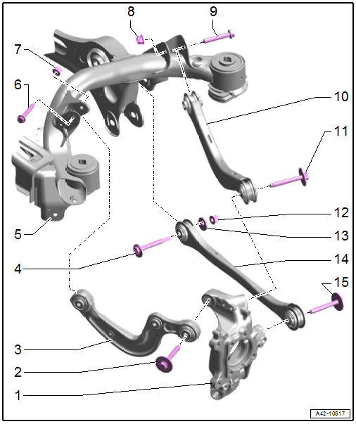
1 - Wheel Bearing Housing
2 - Bolt
- 70 Nm + 180º
- Replace after removing
3 - Front Upper Transverse Link
- Removing and installing. Refer to → Chapter "Front Upper Transverse Link, Removing and Installing".
- Installation position. Refer to → Fig. "Transverse Link and Tie Rod Installation Position".
4 - Eccentric Bolt
5 - Subframe
6 - Bolt
- 40 Nm + 180º
- Replace after removing
- Tighten in the curb weight position. Refer to → Chapter "Wheel Bearing in Curb Weight Position, Lifting Vehicles with Coil Spring".
7 - Nut
- Replace after removing
8 - Nut
- Replace after removing
9 - Bolt
- 70 Nm + 180º
- Replace after removing
- Tighten in the curb weight position. Refer to → Chapter "Wheel Bearing in Curb Weight Position, Lifting Vehicles with Coil Spring".
10 - Rear Upper Transverse Link
- Removing and installing. Refer to → Chapter "Rear Upper Transverse Link, Removing and Installing".
- Installation position. Refer to → Fig. "Transverse Link and Tie Rod Installation Position".
11 - Bolt
- 70 Nm + 180º
- Replace after removing
- Tighten in the curb weight position. Refer to → Chapter "Wheel Bearing in Curb Weight Position, Lifting Vehicles with Coil Spring".
12 - Nut
- 110 Nm
- Replace after removing
- Tighten in the curb weight position. Refer to → Chapter "Wheel Bearing in Curb Weight Position, Lifting Vehicles with Coil Spring".
13 - Eccentric Washer
14 - Tie Rod
- Removing and installing. Refer to → Chapter "Tie Rod, Removing and Installing".
- Installation position. Refer to → Fig. "Transverse Link and Tie Rod Installation Position".
15 - Bolt
- 70 Nm + 180º
- Replace after removing
- Tighten in the curb weight position. Refer to → Chapter "Wheel Bearing in Curb Weight Position, Lifting Vehicles with Coil Spring".
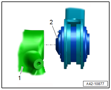
Transverse Link and Tie Rod Installation Position
- The ball side -2- on the transverse link or tie rod must engage in the wheel bearing housing -1-.
Lower Transverse Link
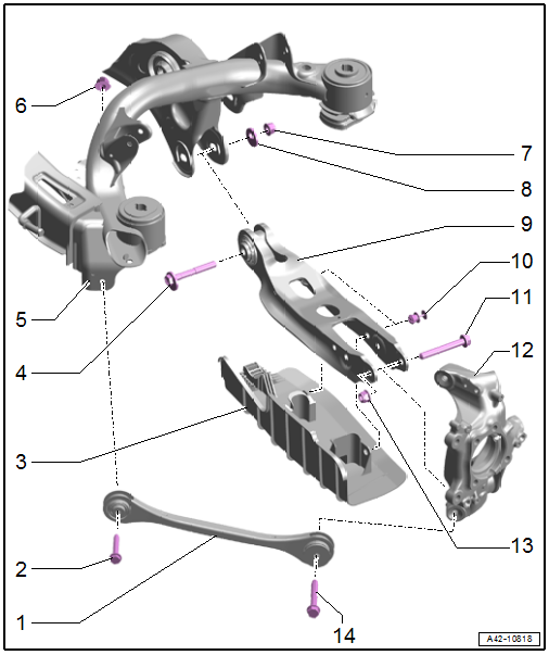
1 - Front Lower Transverse Link
- Removing and installing. Refer to → Chapter "Front Lower Transverse Link, Removing and Installing".
- Installation position. Refer to → Fig. "Transverse Link and Tie Rod Installation Position".
2 - Bolt
- Replace after removing
3 - Wind Deflector
4 - Eccentric Bolt
5 - Subframe
6 - Nut
- 40 Nm + 180º
- Replace after removing
- Tighten in the curb weight position. Refer to → Chapter "Wheel Bearing in Curb Weight Position, Lifting Vehicles with Coil Spring".
7 - Nut
- 160 Nm
- Replace after removing
- Tighten in the curb weight position. Refer to → Chapter "Wheel Bearing in Curb Weight Position, Lifting Vehicles with Coil Spring".
- Loosen and tighten using the 21 mm 6-edge socket wrench
8 - Eccentric Washer
9 - Rear Lower Transverse Link
- Removing and installing. Refer to → Chapter "Rear Lower Transverse Link, Removing and Installing".
10 - Expanding Rivet
11 - Bolt
- Replace after removing
12 - Wheel Bearing Housing
13 - Nut
- 70 Nm + 180º
- Replace after removing
- Tighten in the curb weight position. Refer to → Chapter "Wheel Bearing in Curb Weight Position, Lifting Vehicles with Coil Spring".
14 - Bolt
- 70 Nm + 180º
- Replace after removing
- Tighten in the curb weight position. Refer to → Chapter "Wheel Bearing in Curb Weight Position, Lifting Vehicles with Coil Spring".
READ NEXT:
 Upper Transverse Link, Removing and Installing
Front Upper Transverse Link, Removing and Installing
Special tools and workshop equipment required
Torque Wrench 1332 40-200Nm -VAG1332-
Caution
This procedure contains mandatory replaceab
Lower Transverse Link, Removing and Installing
Rear Lower Transverse Link, Removing and Installing
Special tools and workshop equipment required
Torque Wrench 1332 40-200Nm -VAG1332-
Engine and Gearbox Jack -VAS6931-
Engine/Gearbox Jack Adapte
Tie Rod, Removing and Installing
Special tools and workshop equipment required
Torque Wrench 1332 40-200Nm -VAG1332-
Engine/Gearbox Jack Adapter - Wheel Hub Support -T10149-
Engine and Gearbox Jack -VAS6931-
Caution
Thi
SEE MORE:
Adjusting adaptive cruise control
Applies to: vehicles with Audi adaptive cruise control
You can adjust the system individually. The settings
depend on the vehicle equipment.
Applies to: MMI: Select on the home screen:
VEHICLE > Driver assistance > Audi adaptive
cruise control.
Possible settings:
Applies to: vehicles with
Compressor, Replacing on Account of Leakage or Internal Damage
Vehicles with a High Voltage System (Hybrid Vehicles)
Extremely Dangerous Due to High-Voltage
The high-voltage system is under high-voltage. Death or serious
bodily injury by electric shock.
- Individuals with electronic/medical life- and health sustaining
machines in or on their person canno
© 2019-2026 Copyright www.audia4b9.com
